• Please review our updated Terms and Rules here

IMSAI newbie, no idea what I'm looking at

Ah, you need to work that out for yourself whether switch closed CLOSED is UP or DOWN...

Measure one switch with a resistance meter and the setting that gives 0 Ohms is CLOSED and whether this equates to UP or DOWN now becomes the reference.

Dave
 
thanks, I'll finger it out.

in order to test the 7405 pins above pin 7, I'll need to work out a probe extension or something. these on the bottom row are covered by the switches.
 
this seems to work. a shiskebab skewer I found in a kitchen drawer and some heat shrink. initial run through the 7405 output pins with switches closed (off/down position) and all outputs so far are solid high with the exception of U4-10. no signal. this is the one that I believe is mislabelled pin 12 on the 2014 schematic (it shows two pin 12s, but I toned this one out recently and marked my schematic.

I'll go back through all this tomorrow to validate.
 

Attachments

  • oribeScreenshot 2023-12-28 at 4.21.26 PM.png
    oribeScreenshot 2023-12-28 at 4.21.26 PM.png
    2.6 MB · Views: 3
The U4 socket (old original) pin 10 was not making contact from the chip to the board, failed socket. I'll get it replaced today and see where I stand.
 
Ah...

But I am not sure how that would affect the issues we have seen though. But we need to remove that fault nonetheless.

Dave
 
U4 10 and 11 are 7405 outputs. mislabelled on the new schematic 2014 version as 12 and 13. I have verified the original schematic with 10-11 is correct.

I how have high solid on all the HAD 7405 outputs. pin 10 was the one with no signal, now good.
 

Attachments

  • cpa schem Screenshot 2023-12-29 at 6.49.36 AM.png
    cpa schem Screenshot 2023-12-29 at 6.49.36 AM.png
    457.3 KB · Views: 3
Excellent.

With switches SA0 through SA15 CLOSED. Are all the data bus LEDs illuminated on the front panel?

Dave
 
Last edited:
If the above is correct, here is how I would proceed.

Power ON. HALT and RESET.

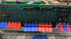
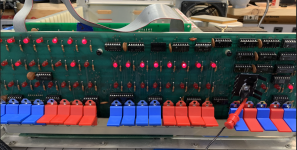
Set all of the switches SA0 through SA15 to OPEN. The data bus LEDs should all be ON.

Power off and remove IC U12 - observing the correct polarity of the IC within the socket for subsequent installation.

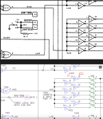
I am 'hoping' that this will cause the LAD signal to float HIGH (due to the action of the weak pull-up resistors on the inputs of the connected 7405 gates).

Power ON. HALT and RESET.

Test signals HAD, C3 and NOOP again (with your logic probe). I am hoping these three signals should all be LOW. If not, report and stop.

In theory - with the 7405 inputs HIGH (due to the signal LAD being pulled HIGH due to the internal pull-up resistors) the outputs from these 7405 gates connected to LAD should all be LOW.

By CLOSING switch SA0 - this should cause the data bus LED D0 to extinguish. The other data bus LEDs should remain illuminated.
By OPENING switch SA0 - data bus LED D0 should illuminate once again.

Repeat this test for SA1 through SA7 in turn (CLOSE followed by OPEN) and data bus LEDs D1 through D7 (respectively) should extinguish and illuminate.

If this is the case, power OFF and re-install IC U12 in the correct orientation (as found). Check for any bent pins on IC U12 after installation.

Report the results.

Dave
 
thank you.

With switches SA0 through SA15 CLOSED. Are all the data bus LEDs illuminated on the front panel?
Yes, all on.

Test signals HAD, C3 and NOOP again (with your logic probe). I am hoping these three signals should all be LOW.
all test low.

By CLOSING switch SA0 - this should cause the data bus LED D0 to extinguish. The other data bus LEDs should remain illuminated.
By OPENING switch SA0 - data bus LED D0 should illuminate once again.

Repeat this test for SA1 through SA7 in turn (CLOSE followed by OPEN) and data bus LEDs D1 through D7 (respectively) should extinguish and illuminate.
quick try of this. works on all but 1 and 6 (edit, not 7). I will check the switches again unless you see anything obvious.
 

Attachments

  • Screenshot 2023-12-29 at 10.11.02 AM.png
    Screenshot 2023-12-29 at 10.11.02 AM.png
    3.6 MB · Views: 4
  • Screenshot 2023-12-29 at 10.10.48 AM.png
    Screenshot 2023-12-29 at 10.10.48 AM.png
    3.3 MB · Views: 4
Last edited:
I can't see anything obvious.

It could be that the 7405 logic gate output associated with these two switches is not being pulled low (test with the logic probe), the two switches are not making a good connection, the inverter buffers driving these two data bus LEDs are broken (the output is always LOW) or there is a PCB fault (or IC socket fault associated with the two inverter gates driving the data bus LEDs).

A few things to be checking there...

Out of interest, can you follow what I am trying to test by following the schematics?

Dave
 
Just to set the scene a bit more...

If the output from any of the 7405 inverters driving the common bus is LOW (and - in the case of the SAn switches - the associated SAn switch is CLOSED) this will pull the common bus bit LOW.

A HIGH on the common bus bits will illuminate the data bus LEDs.

Also note that the 7405 inverters driven by the C3 and NOOP signals can also affect the common bus - as they are all wired together.

If you suspect an inverter, you can remove the IC package. Just beware as to what the other gates within the inverter package are driving...

Dave
 
it makes sense, and I will learn from your methodical approach. but I can't say (yet) that I could come up with your approach!

after fighting some 45 year old solder joints and terrible sockets, I'm back to S0-7 toggling data leds 0-7 as you describe with U12 removed.

yay.
 
Excellent!

So, re-install IC U12 (if you haven't already) and repeat the same hassle (!) by removing IC U14 driving the HAD signal.

Make sure switches SA0 through SA15 are all OPEN.

Again, STOP and RESET.

Check that signals LAD, C3 and NOOP are all LOW.

Repeat the same process using switches SA8 through SA15.

SA8 should drive data bus LED D0 and SA15 should drive data bus LED D7 (with all of the inbetween SAn switches driving the other data bus LEDs in the same way).

Dave
 
SA8 should drive data bus LED D0 and SA15 should drive data bus LED D7 (with all of the inbetween SAn switches driving the other data bus LEDs in the same way).

this seems to work as described with U14 out. left most switches control the right most LEDs.

couple of oddities to me:

with all chips in run/stop works. with U12 OUT stop does not halt. with U12 in, U14 out run/stop works.

with U12 out, LED 6 stays partially illuminated. the corresponding switch up turns it to full bright. off and it dims but does not go totally out. with U14 removed, all LEDS turn fully on and off.
 
There may be other parts of the device that we removed used elsewhere...

Which LEDs are you talking about when you say left most switches control the right most LEDs?

We are using the address switches to modify the data bus LEDs, not the address LEDs.

Dave
 
There may be parts of U12 that are used to upset the operation of the RUN/STOP switch if U12 is removed.

There will be a way of forcing the CPU to STOP. Let me look at the schematic...

Dave
 
I am not sure I am getting what you are telling me.

U12 is only used in the derivation of signals HAD, C3 and LAD. As such, removing U12 should still cause RUN/STOP to work OK.

U14 is used in the derivation of HAD, XRDY, DEPOSIT and EXAMINE. I could see this upsetting the RUN/STOP logic.

What you say back in post #55 is the complete opposite of what I think should happen.

Ditto for the data bus LEDs.

We should be able to fully turn all of the data bus LEDs OFF. But we may not fully illuminate them if the CPU is accidentally running.

That is my assessment at least.

Dave
 
thank you for your help and patience. I'll get back with a fresh status in the morning and try to clarify where it stands based on your requests.
 
Hi Dave
I've not had time to read all the replies. Have there been any test to see if it is a problem on the front panel side or the bus side.
Has the 2 switch been used for addresses?
I was off on a trip and not had access.
Dwight
 
Back
Top