• Please review our updated Terms and Rules here

KIM-1 repair

powerlot

Veteran Member
Joined
Nov 20, 2021
Messages
549
Location
Europe
Hi all

I treated myself to something I wanted for a long time: a KIM-1 :)

Unfortunately, it's dead...

I found the CPU is broken by swapping it with a Synertek one out of a working Apple IIe (the MOS one shows striped bars on the A2, so it's clearly kaputt).

Now, when pressing reset it either briefly flashes all "8"s on the display and then nothing, or sometimes one of the digits shows one 8 in a random loation and the current draw goes up by 150mA-200mA, from hovering around 500mA


Any ideas where to start troubleshooting?
 
Nice acquisition!

I am guessing the CPU has halted. You can check this by monitoring pin 7 (SYNC) of the 6502 CPU.

The displays are supposed to be multiplexed but, if the CPU halts, one of the digits could be left ON and the current increase as a result.

My pure guess at this point would be bit rot of the ROMs (largely irreplaceable unless you use adapters) or a RAM fault.

@Dwight Elvey has an external KIM tester EPROM available if I remember correctly.

Dave
 
If you do a search for "kim-1 dwight" There is a lot of good reading.
First, the fact that the CPU was dead is potentially a bad indicator. In my case, it was clear that someone had connect the voltages inverted.
The -002 chip was also wiped out.
Still, of those that got my original kits, no other case was a 6530 chip. The most common was one or more of the RAM's.
There were a couple random IC as well.
If you search through the pages, you'll eventually come to pointers of the schematic for the debug board and the EPROM code.
There is not much to the board and it can be easily wire wrapped or even point to point created.
The higher current might tend to indicate contention. Places to look might be RAM areas or the address decoder chip giving multiple selects.
I just thought I'd mention ( not knowing how much you know about the KIM-1 ) there are two pins on the one connector that have to be jumpered for the KIM to run.
Although, the thought of a 6530 being bad, there are a few options for adapter boards out there.
I created an adapter. My intent was to create one that fit in the foot print of the original 6530. One of the other posters has documented the adapter.
If you look at the wiring schematic you'll see a few strange wiring connections for things like the EEPROM. These were done for two reasons.
One was routing everything under the 6532 chip and the other was to be able program the EEPROM on the KIM, using the debug board.
Other adapters, by others, are larger boards using more standard PC boards.
Anyway, back to the debug board. One of the problems of the 6502 is that it is basically brain dead without RAM on page 0 and 1.
The debug board has a number of test that you select with switch setting on the debug board.
The first test is to check that the data and address bus is working well enough that the processor can run.
It is not a conclusive test of every address bit but just a starting point. If the processor can blink a light on the debug board I consider that as a start.
Next is a main RAM test. Now you can't run a RAM test using RAM so the test is a simple pattern test using only the processors registers and a blinking light.
Once there is working RAM, other parts are tested. There are a few things that are not test as, if it gets that far, you can test the rest from the KIM itself.
I thought I'd mention, I'm not in the business of making any more adapters. I made one for myself and created 10 more to average out my cost.
Besides, I'm 76 years old and have other projects I'd like to complete before being terminated.
Anyway, read the other stories.
Dwight
 
Thank you both for the tips. I did some skimming through the other threads but I don't know anything about KIM-1s except for some basic knowledge about 6502s.

I assume these are the latest design files about the debug board? http://retro.hansotten.nl/6502-sbc/kim-1-manuals-and-software/kim-1-diagnostic-board/

I'll try to have a PCB fabricated and get all the parts for it.

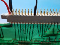
For the connector, I followed the user manual and it looks like this:

kim-1-1.jpg
 
Thanks Dave, I was confused about the missing letters in the alphabet, and went for the 'K' on the connector. Maybe someone here knows why those edge connectors are missing some letters?

The BOM for the debug board is in 'DBGBD.TXT' of the above blog post.

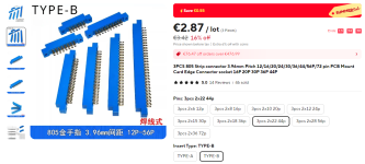
I found these connectors:

1719124120626.png

The 'type B' connector with the little holes should be better for soldering directly to the PCB edge connector, no?

I'll be back in few weeks when I have the board assembled and programmed
 
The missing letters are by design to prevent people mistaking some letters for numbers. For example 'I' and '1' look very, very similar.

Hence, som alphabet characters are missing.

Look at the DEC PDP backplanes for other examples.

 Dave
 
Thanks Dave, I was confused about the missing letters in the alphabet, and went for the 'K' on the connector. Maybe someone here knows why those edge connectors are missing some letters?

The BOM for the debug board is in 'DBGBD.TXT' of the above blog post.

I found these connectors:

View attachment 1281933

The 'type B' connector with the little holes should be better for soldering directly to the PCB edge connector, no?

I'll be back in few weeks when I have the board assembled and programmed
Bend the pins down to the board, don't expect to hold the terminal down to the board with solder to hold it to the board and tension, between the pin and board. The connector solder side should naturally hold against the board or at most have a small solder filled gap. Solder is not a solid connection, it is just a electrical connection.
Also make sure the connector slides onto the KIM's connector before soldering to the diagnostic board. I found the several connectors with the correct pin spacing will not fit the KIM board and a little additional opening of the connector ends. I did this with a bur tool on my Dremel tool.
You do have to remove the end connector pins as they will be easily damaged,working so close to them.
They relatively easily push out by needle nosed pliers on the solder side. You should only need to remove the two nearest each end when you are expanding the end opening of the connector socket. I suppose it might be possible to use a small end mill bit with a vice to hold it and a drill press or mill. If you wanted to I suspect you could remove more pins, as far as the blade will go, and use a narrow saw blade. Once it is enlarged you could glue a small piece to fill in where too much was removed. The blade needs to be wide enough to let the KIM board to clear.
There is a little trick to putting the pins back in. If you just try to push them back in, without a little help from a "special" tool, you will bend and damage them.
What I find works as a good special tool is a credit card slid to the pc board slot of the connector then push the sockets connector back in. The credit card ( special tool ) is the right thickness to keep from bending the spring part of the connector piece while sliding it back in place. I find the once it is part way in, I can then use the needle nose pliers to pull them the rest of the way from the solder side.
Of course, if the connector fits the KIM fine, you can ignore the end expanding tricks. I don't know why they had the reduced connectors, it is just what I found.
There is a position on the diagnostic board for normal operation of the KIM so you don't need to remove it for normal operation. In the ROM, each test code only need a small amount of memory. Most all the test have additional space in the EPROM. I put two of Butterworth's programs in the empty spaces of the ROM. I forget where but there is a "Master Mind" and an Astroids game. I like the Astroids one the most. They do have to be relocated to the empty space in the EPROM space that is selected to run. I just hand relocated his programs as they were quite small. Of course, one could reassemble other ones in other locations. The switches put a 1K part of the EPROM in memory, at 0E000h as I recall there is always a small boot vector at the end of each test section. These are only active it the test boots from the EPROM by the switch selection. If not selected to boot, one can run anything in the 1K that the switches select, like the games I put in there :)
Dwight
 
The missing letters are by design to prevent people mistaking some letters for numbers. For example 'I' and '1' look very, very similar.

Hence, som alphabet characters are missing.

Look at the DEC PDP backplanes for other examples.

 Dave


Curiously a similar scenario cropped up in Europe.

I once had an email from a guy in the USA and he was looking at one of my schematics and was baffled.

He said he had worked in electronics for more than 50 years in the USA. He could not understand that I labelled some resistors in what he thought was a non-standard way, that he had never seen before.

For example I labeled a 4.7k resistor on a diagram as 4k7.

This nomenclature was very popular in Europe, especially by Philips and was common on most of their schematics.

What was the purpose ?

It appears similar to the issue of I's and L's and different fonts being confused, or perhaps the fact that the dot, say in a number like 4.7 could disappear in poor copies of documents, so it made the notation of 4k7 to be more foolproof.

What about the name Illinois, except for the font where an "I "appears as an "l "(now how would some lunatic down in Australia even know this ? but of course we watch the Fugitive movie and drink a lot of beer too, so our powers of observation are improved), but the first letter is an I and the second two letters are L's, see attached, but it reads as lll(small i)xxxx.
 

Attachments

  • ILL.jpg
    ILL.jpg
    61.3 KB · Views: 9
Last edited:
>>> For example I labelled a 4.7k resistor on a diagram as 4k7.

It is more interesting than that of course. In the UK (in old money) it would be 4.7k. In certain countries in Europe it would be 4,7k. 4k7 harmonises it and (as you mention) gets rid of the '.' getting accidentally erased. Of course, a ',' is not much better either in this respect.

Dave
 
I don't know how anyone could have worked in electronic, for 50+ years, and never had seen the notation of 4k7 before. I guess he didn't look at schematics before.
Dwight
 
I have received my parts from DigiKey and the connector from Aliexpress.. now only the PCBs are missing.

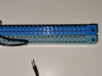
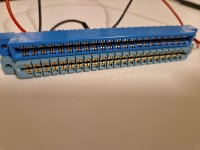
Thanks for the tips about expanding the connectors. Fortunately it fits... but there are few traps: The lettering doesn't match the manual and it's upside down. There's also a bit less "meat on the bone" regarding the metal tabs inside.

kim-1-3.jpg kim-1-2.jpg

It looks good otherwise...

I don't know how anyone could have worked in electronic, for 50+ years, and never had seen the notation of 4k7 before. I guess he didn't look at schematics before.
Dwight
I haven't worked in electronics in my past, but when I saw this in an old schematic (very possibly a Philips or some German vacuuum tube radio) it made perfect sense why this was done.

When I have the board assembled and the KIM-1 working I would be interested to see how to play games
 
Or write some games yourself...

My first game was the venerable 'duckshoot'.

You can also add a digital to analogue converter to the user port so you can play music...

Dave
 
They had several different solder side pin types. The wire connections were a little short. The wire wrap were a little too long. Just getting a connector is a pain. They like to obsolete everything. I was looking over the instructions and see that the address I posted, here, for the games was incorrect, Follow the written instructions.
I should have mentioned that the diagnostics don't point you to the actual problem, you are expected to use a scope or meter and look at things.
One other thing that I didn't mention in the instructions ( I didn't think about it ) is that if the RAM test shows alternating bad RAMs, it is likely the address decoding that is failing. The test stops on first failure and the data patterns are 55h or AAh ( forget which is first ). A completely dead RAM will look like alternating RAMs failing.
You'll have to forgive the simplicity of the RAM test. Like I said, the 6502 is brain dead without RAM, at least on the 0 page. For the RAM test I use every register in the 6502 without depending on the RAM that may not be working. It is one of those chicken and egg problems.
I'm surprised about the pin labels. It is likely that these were reject connectors ( the reason you can still get them ). Someone made a batch of them so they sat on the shelf for years before someone realized that people still wanted such pin spacing. It wouldn't be until someone was actually looking at the pin's labels that anyone would care.
Dwight
 
kim-1-4.jpg
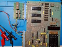
The PCBs arrived, the deed is done. Unfortunately nothing is happening, still and I'm far away from playing (or programming) any games here. I'm not sure which file to burn on the EPROM. I used "kimdiag.bin" from the blog post, checksum 42d9.

I should have mentioned that the diagnostics don't point you to the actual problem, you are expected to use a scope or meter and look at things.
With the switches all ON, I should get a blinking LED, right? It's not happening.... I have no clue where to start debugging

I've been saying for a while Chinesium edge-connectors are brittle crap, but no one listens.
They're fine for hobby use... I've never had actual problems with them, it's noticeably lower grade but not bad per se.
 
I'm not sure which file to burn on the EPROM. I used "kimdiag.bin" from the blog post, checksum 42d9.

I read my KIM-1 Diag 1.0 ROM from one of Dwight's original units and the checksum is 42d9 so that looks correct. I've used it to fix multiple KIM-1s.

With the switches all ON, I should get a blinking LED, right? It's not happening.... I have no clue where to start debugging
If you've checked voltages on chips on the KIM-1 and they look fine, that would indicate a bad 6502. If there is a way to test the 6502 in another computer, it would be a good test but not ultimate. I had a 6502 that checked out okay but it was not good enough for the KIM-1.

Good luck.
 
I already swapped the CPU out of a working Apple IIe and verified the original was bad.
What else could prevent it from executing code? Reset and clock appear in order, nothing draws excessive current
 
Check the NMI and IRQ pins (they should not be permanently LOW - HIGH or pulsing).

Check CPU pin 7 (SYNC) and see if it is pulsing. This indicates it is executing instructions.

The most likely issue is a faulty address or data line. If something is 'forcing' a data bit LOW (for example) that would be a bad day for any program!

Less likely to be the address lines. More likely to be the data lines.

If U2 or U3 (6530) or U13 or U14 (74125 buffers) are accidentally driving the data bus when they should not be - this could account for your problem.

I would check U1 (CPU) pins 2, 4, 6 and 40 for being HIGH.

You say RESET is working (CPU pin 40 goes LOW when operating the RESET button).

The problem is you may have a "chicken and egg" situation. You really want to know what is exactly happening immediately following a RESET condition. Is the CPU fetching the correct reset vector from the firmware or not? Does the CPU start to execute instructions correctly and then go off into the weeds?

Do you see any activity on CPU pin 7 (SYNC) after you press RESET? You will need a logic probe (with a pulse catcher) or an oscilloscope for this.

Dave
 
Last edited:
Back
Top