falter
Veteran Member
Darn.. couldn't be that easy. I replaced the broken 1k resistor but yeah, no change. Darn!
| VCF West | Aug 01 - 02 2025, | CHM, Mountain View, CA |
| VCF Midwest | Sep 13 - 14 2025, | Schaumburg, IL |
| VCF Montreal | Jan 24 - 25, 2026, | RMC Saint Jean, Montreal, Canada |
| VCF SoCal | Feb 14 - 15, 2026, | Hotel Fera, Orange CA |
| VCF Southwest | May 29 - 31, 2026, | Westin Dallas Fort Worth Airport |
| VCF Southeast | June, 2026 | Atlanta, GA |
You leave it off in some cases if/when you expand the system. IIRC the KIM-2 RAM board I had required you to remove it.
Hi glitch,
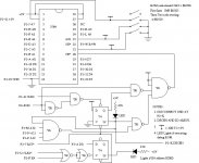
Yes, but typically a better way of doing this would have been to design it such that an open circuit at this pin K would allow internal operation and then a ground would be required to allow for expansion. This could be accomplished with an inverter and a pull-up resistor on the DECEN signal.
-Dave
") I'm getting ready to test a S-100 clock board that expects you to jumper whatever AC voltage is ahead of the +/-16V rectifiers onto the bus! "Sane defaults..." right?
I'm getting ready to test a S-100 clock board that expects you to jumper whatever AC voltage is ahead of the +/-16V rectifiers onto the bus! "Sane defaults..." right?Darn.. couldn't be that easy. I replaced the broken 1k resistor but yeah, no change. Darn!
Of course, but this is old computers
") . You are right. Old computers can be fun!
. You are right. Old computers can be fun!The logic could easily be put in a 16R4 but I'm too lazy
to deal with it.
Which part is -003 and -002?
Is U2 = -002
and U3 = -003?
or the other way around?
Dwight
I checked pin 10 of U16 (7404). I do have a pulse there.
I don't know if U26 is important to be 1 or 0 for the
computer to run.
It is part of the tape read.