• Please review our updated Terms and Rules here

KIM-1 Repairs continue

Another thing.. I have just 6 74125s on hand. I have noticed that depending on which is installed, the signal on the address lines picked up can change. For example with one particular 125 installed, it's a very fast beep. But with another, it's slow. I'm wondering if possibly none of these 125s is completely good.
 
So this pin indicates that the CPU is executing instructions if it is pulsing. If it is LOW, the CPU has given up.

If it starts pulsing after a reset, and then just stops, it is invariably not executing the correct program from ROM.

Dave
 
So this pin indicates that the CPU is executing instructions if it is pulsing. If it is LOW, the CPU has given up.

If it starts pulsing after a reset, and then just stops, it is invariably not executing the correct program from ROM.

Dave
Thanks Dave. What does it mean when it starts immediately on power up and doesn't stop except when reset is held?
 
Thanks Dave. What does it mean when it starts immediately on power up and doesn't stop except when reset is held?
It means the CPU is executing instructions continuously. Of course, it may be executing cr*p!

You can use your logic probe on the various chip select pins to see what devices are being selected. It should, of course, be executing code out of ROM. If none of the ROM is being selected, the CPU is executing cr*p.

This is one reason why a NOP generator is useful at testing out that the CPU runs reliably and that the chip select logic works correctly.

Dave
 
This has been along time since this was posted. I've not put any more debug kits together since I made 10 kits and sold them.
If you search a little one of the others on the forum made some stuff for the debug board. I used KiCad and was transfer files to a safer place and accidentally deleted the design files ( what a dummy ).
It came with two small board that had a EEPROM, 6532 and a PAL. This could be used to replace a bad -002 or -003 chip.
I don't know if the debug board schematic on this thread is correct ( it has been a long time).
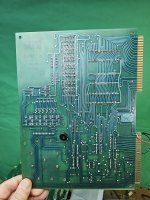
If you've put sockets on the KIM, there is a good chance you've broken traces ( I'm a experienced board repair and opened 2 traces when I put sockets on the board ).
Let me see if I can find the relevant thread.
Dwight
Thanks Dwight. I regret I didn't leap on that at the time but got busy with other things.

And yes I've definitely done some trace damage which I've had to repair. I was terrible with desoldering years ago when I first worked with this board.

I might try the NOP generator Dave suggested to troubleshoot further, as well as testing the 125s on a breadboard.
 
You can see pictures of the small boards I made in place of the Corsham boards.
I might have a bare board set left but I'll need to see if I have the fuse file for the PAL.
I think I have a couple of the tiny EEPROMs used. They are in flat packs and to get things small enough, I fold the leads under the chip. One needs to planerrize the leads with fine sand paper and re-tin them. In the kits I sold, I did this myself and soldered them to the small boards because it is tricky to do without making a mess.
Any way, you need the debug board to program the EEPROM for -002 or -003.

You can get the debug board schematic from the first one. It only has a few parts and can be easily created.
If you build the debug board and you find the 6530 chip bad, I'll see if I can put together enough parts to make one of the small replacement boards.
In the one picture, you can see my prototyping where I made a rats nest to prove the concept.
 
It means the CPU is executing instructions continuously. Of course, it may be executing cr*p!

You can use your logic probe on the various chip select pins to see what devices are being selected. It should, of course, be executing code out of ROM. If none of the ROM is being selected, the CPU is executing cr*p.

This is one reason why a NOP generator is useful at testing out that the CPU runs reliably and that the chip select logic works correctly.

Dave
When I probe CS1 and CS2 on both 6530s I get a solid HI signal on the logic probe. I can see CE pulsing. Following my concerns about the 125s, I took out the KIM-1 schematic and probed the three pins that connect to each chip (Data In, Out and I forget the third). Sometimes some pins didn't have pulsing, sometimes they did. I tried swapping chips to see if the pins that weren't pulsing on a given chip remained that way when swapped to the other location. But it was totally random. Sometimes you'd hit reset and you'd see pulsing for a couple seconds on one of the 125s pins and it would stop, and then again and it would pulse indefinitely.

I think you're right Dave.. I think the CPU is just executing random stuff that it thinks is there and sometimes it hits something that stops it. So I guess that's where this adventure ends unless I stumble across an replacement RRIOT chip.

I wonder how hard it would be to dump the ROMs to verify?
 
There are a number of things you can do in the meantime:

1. Test the keyboard matrix.
2. Test the 7-segment displays.
3. NOP generator to test the address lines and the address decoding.

You can remove each 6530 and use a little circuit on a plug board (switches and LEDs) to readout the ROM contents. It is a pain, but it can be done.

You can still purchase 6530 replacement PCBs utilising a 6532 and an EPROM. It is probably simpler buying 2 of these now even if your 6530s are good (now). They may fail in the future, and you are prepared!

This really just leaves the RAM and buffers...

I can explain 1 and 2 in a later post. 3 is simply done with a spare (cheap plastic) 6502 CPU with the databus pins bent out and connected in the pattern $EA. Then swap the 6502 over.

Dave
 

You can get the debug board schematic from the first one. It only has a few parts and can be easily created.
If you build the debug board and you find the 6530 chip bad, I'll see if I can put together enough parts to make one of the small replacement boards.
In the one picture, you can see my prototyping where I made a rats nest to prove the concept.
Dwight:

I wanted to drop you a pm, but since I've been lurking here for years and this is only my second post, I can't.

I just wanted to ask whether the files on Hans' site are complete and current, particularly the diagnostic EPROM binary and the corresponding instructions. Since I ran across your package (I have a couple of KIMs on the bench I want to exercise), in a fit of pique I redrew the reverse-engineered schematic and figured I'd format your guide to the debug for the benefit of others.

Jonathan
 
Thanks Dave.

So what I've done so far:

1) I looked at the schematic and began testing where the keys connect to U24 and that they activate pins on that chip when pressed. All keys seem to produce something there.
2) I've been able to haphazardly light individual LED segments on the various LEDs - I think my probe accidentally triggered the transistors as I was checking things. I don't fully understand how it works, but at least some parts of them do.
3) I am reading up on how to do the NOP generator. I do know for certain the CPU itself works - it has been removed and tested in another machine.

I have a ton of 6532s and 6530s. I even have one of the two ROMs - the 6530-003. I don't know if the KIM is completely dead without either -003 or -002, I think -002 was the critical one? I believe I tried swapping the 6530-003 before but maybe my address lines being crossed vexed things.

Many thanks for your patient help as always. I've noticed the KIM has suddenly become very valuable and I feel bad letting it collect dust on a shelf.
 
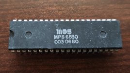
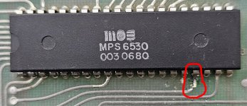
Stupid question. This IS the correct 6530-003 for the KIM, right? There was only one -003 part number, they didn't reuse it for some other ROM? I'm suspicious because the date code is late (were they still producing KIM-1's and parts in 1980?).

I had thought I had tried replacing this already. There is evidence I at least attempted to desolder the original -003, but I see no solder at all on this chip, which I know for sure is not the original. I would expect there would be clear evidence of that if I had installed and then removed it without a socket. Hmmm.

I'm also not sure of the status - all of my many Commodore/MOS chips came from the estate of a retired Commodore repair person. The majority of the Commodore/MOS chips have clean, gleaming pins like this one which suggest they were never used.

Second question - the KIM-1 will not function at all if this one is dead right? Or would it be partly functional?

20240102_190824.jpg
 
AIUI U2 (the -003) controls the keypads and LED, so you'd effectively have a dead KIM. I do not know of any other -003 variant.

I haven't tried it with the KIM RRIOTs personally, but I do have a BackBit chip tester, and it does claim to be able to test RRIOTs including the ports, RAM, ROM, timers and interrupts. Not the seller, just a customer. At least that would give you an idea if you had a working chip to begin with. See https://store.backbit.io/product/chip-tester/ and http://backbit.io/downloads/Docs/
 
U2 is the -002 - I'm not sure exactly what -003 does. It's a bit confusing because you think physically it'd be in order, U1 to U3 from top to bottom, but it goes U1, U3 and then U2. I have a bad feeling U2, the -002 is my actual problem. But I have this spare -003 here...

I see on the schematic U3 mostly seems to be connected to the user port. But I wonder if it's messed up if it can hang the whole system.
 
No worries. In the event, I swapped the -003, just since I had nothing else to try.. but alas it did not change things. I think we are coming down to -002 unless there is something else I've missed.
 
Let's go back to the basics - since there appears to be some major confusion with the 6530's in your memory.

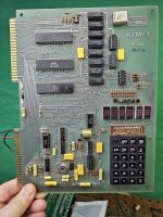
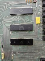
Can you post a photograph of U1-U3 in the PCB so I can see the orientation of the chips and the numbers on them.

There are some good gotchas here with the KIM-1 that you may have inadvertently fallen into by swapping stuff around.

I will explain when I see the photograph...

Dave
 
Here are four pics showing the whole board and U1-U3. Please excuse the horrible soldering job on the back side.. this was mostly done when I was still learning how to desolder/solder things. I've gotten much better since.
 

Attachments

  • 20240103_085923.jpg
    20240103_085923.jpg
    2.8 MB · Views: 12
  • 20240103_085932.jpg
    20240103_085932.jpg
    2.8 MB · Views: 12
  • 20240103_085940.jpg
    20240103_085940.jpg
    2.1 MB · Views: 13
  • 20240103_085943.jpg
    20240103_085943.jpg
    2.5 MB · Views: 10
Back
Top