• Please review our updated Terms and Rules here

My "new" Northstar Horizon: where to get started?

The light bulb may protect things but are too low a resistance to protect the large electrolytic capacitors. They likely need to be reformed. If you hit them with the full voltage, even though they may not fail, the inrush of current will be so high caused by the new voltage forming the oxide barrier, that it will out gas heavy enough to damage the seals ( the little gray dots on the end ). These are intended to blow if the pressure builds to fast. Still, some out gassing does always happen in electrolytics. It is mainly a problem of how much and how fast. Once the seal has burst, the electrolytic will eventually dry out and be no good.
Please use the procedure I gave you. Don't be in a hurry. any form of light bulb will not let the electrolyics reform slowly enough that they will do it in a healthy way.
Dwight
 
Okay.

Just so I’m 100% clear, the resistors should go between the leads from the transformer and the capacitors? Just on the hot side, leave the grounds wired up as normal? That should be easy enough. I assume I can leave the output unloaded during this.
 
I would disconnect the capacitor myself and use a separate variable dc voltage bench power supply and a series resistor in-line between the power supply and the capacitor.

There are a number of websites describing this process. For example https://www.qsl.net/g3oou/reform.html.

This has worked for me. I just avoid capacitors that are bulging, leaking or rusty...

When you are happy that the capacitor has “reformed” I would set the dc power supply to the same value as the dc rail to which the capacitor would ordinarily be connected to, but without the series resistor.

The advantage of using a bench power supply unit is that you will probably have a current limit feature. Start off with a low limit, and increase it if things look ok.

If you are still happy, put the capacitor back in the N*H and repeat the process for all of the others.

When you have reformed them all, try with the N*H power supply itself and see if you get sensible, unregulated dc voltage rails without the fireworks!

Check (with an oscilloscope) that the capacitors are not open circuit, and are performing their smoothing function.

That’s my advice.

Dave
 
Last edited:
I would disconnect the capacitor myself and use a separate variable dc voltage bench power supply and a series resistor in-line between the power supply and the capacitor.

There are a number of websites describing this process. For example https://www.qsl.net/g3oou/reform.html.

I've been looking for an excuse to get a decent bench power supply, so maybe I can use this as the occasion to pull the trigger; I'd probably get a lot more use out of that than an AC variac.

So, basically, undo the capacitors from their transformer feeds, hook them up to the DC power supply, put the current limiting resistor on the *negative* side, and allow to cook while regularly checking the meter to see the voltage drop across the resistor trends downwards significantly? The linked recipe recommends a larger resistor for lower voltages; the example it tosses out is a 10k for 25v, for 8/18v... I think I have some 20-100k lying around, although they might be on the low wattage side. Sure I can scrape up something.

(And in the case of the capacitor that's on the -18v line I should put the positive voltage on terminal that's currently connected to the black *ground* wires in the harness and negative on the colored wire, correct?)

Is the thing I gain from the bench power supply instead of just sticking in the current limiting resistors in in front of the transformer leads is another layer of current limiting and/or the ability to ramp the supply up gently to the target voltage? Or is it that "smooth" DC from the PSU is better for the reformation process than the bouncy output from the diodes in front of the transformer?
 
Some pictures from yesterday. Here's an extreme closeup of that nasty gunk I found all over the solder side of the motherboard. I assume it's ancient flux residue:
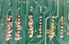
goop_extreme_closeup.jpg

There's also some on the component side, especially around the power supply connection lugs and on the jumper points. (The wires running to the toggle switches on the back panel are visible in this photo, note the brown gunk on the baud rate selection pad.)
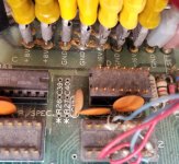
power connections.jpg

It was really thick on the serial connector solder pads:
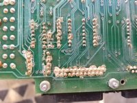
serial_before_cleaning.jpg

It does pick/wash off (after picture of the serial connector below), but it's pretty stubborn. Where it comes off the board *looks* pretty much unharmed... I hope, anyway. Is there a safe solvent that would assist in getting this stuff off?
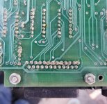
serial_after_cleaning.jpg

Here's a top view of the motherboard before I took it out. Other than a couple dead bugs it was mostly just dusty, so it doesn't *look* like there were any mammals living it, at least.
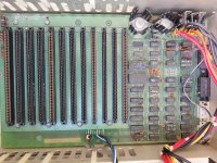
motherboad_top.jpg

... which is why the disgusting appearance of the disk drives was kind of surprising. On both drives the bare metal of the drive chassis were covered with a chalky/scaly white deposit:
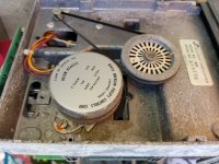
drive_bottom_2.jpg

The loose scale wipes off fairly easily but the metal underneath does seem like it's mildly corroded, and some other parts of the computer had/have a white film on them that seems to be dust from whatever was going on. The plate that the drives screw to in the bottom of the machine actually has some significant deposits of this crud built up on it that don't want to come off. See this picture, taken after putting quite a lot of elbow grease into trying to get the stuff off; it definitely seems metallic in nature:
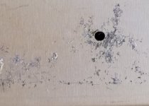
drive_plate_junk.jpg

There was a dead bug stuck to one of the belts but other than that there's not a lot of evidence that something was in there peeing on things, so I'm sort of at a loss. Could this be the result of being stored in humid conditions, maybe salty air? Whatever was going on it *only* really seemed to be attacking the drive chassis; for instance, the cases of the big electrolytic capacitors look perfect. There is some surface rust on the transformer as well, but it's superficial compared to whatever happened to the disk drives.

Other than the crap all over the big casting the drives look like they might be salvageable; the spindles spin freely after the belts were unstuck and the head mechanism looks okay; even the foam pressure pads look like they're still "okay", but most of the floppy disks I have look like they may have suffered badly from whatever storage conditions might have contributed to this scale. :/
 
... Also, re: my earlier speculation that this was built from a kit instead of pre-manufactured, in addition to all that flux residue on the motherboard it may be significant that the S-100 slots are populated by at least two different kinds of connectors. Although, actually, from the condition of the soldering in that area of the board I wonder if it's possible that the connectors with the brassier contacts were installed to resolve some kind of reliability issue? Three out of four of the cards were installed in those slots. There's also a bodge wire on the bottom of the motherboard that seems to be there to resolve a broken trace.

(It may also be significant that there's that CompuPro terminator installed? By board copyright date it's the newest component in the machine, I think.)

EDIT: Apparently I'm blind, because it was only a significant time after posting this thread I realized that the forum has separate sections for "CP/M" and "S-100". If a moderator thinks it would be apropos to move this thread to the other section by all means do so.
 
Last edited:
It doesn't matter which side of the capacitor the resistor goes on except there are usually more wires cross connecting the ground wires. Dave's method works well but most bench supplies are not easily adjusted to 10 milliamps or less. Most of the large computer capacitors are only rated for about 5 to 20 milliamps at most. Still, the combination of supply voltage adjustment and resistor to current limit.
The 100K resistor will be slower but safer. If using an adjustable supply, you can keep the current to around 1 milliamps, with a lower sized resistor.
In both cases, you want to remove the wires to the mother board, going through the frame of the S-100. We'll deal with those later.
Remember, take a clear picture of where the wires go. If the kit was put together correctly, they should all be color coded.
You can ask to move to the s-100 but most people read all the new post. It will be better for the future use of the thread with searches.
Dwight
 
I should note, using Dave's method, remember the polarities of the capacitors. The two smaller ones are connected oppositely. One has the + to ground and the other the negative to ground. You stick them in backwards and the capacitor is destroyed. They don't last long being in backwards.
Dwight
 
I have a Northstar Horizon, and also one of the DeRamp Virtual Sector Generators. I can confirm that the DeRamp VSG works like a champ!

smp

I use the same wonderful DeRamp VSG with my new old stock 5.25" disc drives . It works perfectly with my Northstar double density controller card (in a SOL-20) and the great thing about the VSG is that it is transparent to hard and soft sectored disks, so you could use both, if your drive supports both.

On that N* controller card, it is worth cleaning the IC pins (the narrow sides of them especially if they are in TI sockets that grab the pin from side to side).

The only issue I found was with my particular IBM disk drive units, is that they detect hard sectored disks and disable the use of them due to the chipset & pulse gating they use. However this has not held me back as I simply use soft sectored ones. I think I could modify this feature but I have not got around to doing it.

I put the two drives in a box with the VSG inside:

http://worldphaco.com/uploads/EXTERNAL_DUAL_5.pdf
 
Okay. So, I’ll take inventory of what I have to work with and what I need to buy to do it with using an external supply instead of the transformer outputs. The power supply wiring is in very good shape as far as I can tell and I have copious pictures of the harness so I should be able to easily set up to do the cans one at a time. (The caps appear to have screw lugs on top so it’ll come apart without soldering.)

If I only need milliamp-level currents I probably have some adjustable wall wart power supplies that I could use if I have the suitable resistors on hand. With one of those I could take the voltage up in steps from 1.5v to 12v, at least.
 
On the drives, it is most likely corrosion from temperature cycling in someones garage. Remove as much of the loose stuff that you can. You don't want that stuff to fall into the disk.
On the flywheels, make sure they are clean. Often times when the belts stick to them, it leaves lumps and there is clearly oxide on them. Use a dull knife with the blade at a radial line to scrape the surface where the belt goes. Don't try to shave it or you may dig into the flywheel. You just want to get it to a smooth surface. It is OK to have some corrosion pits, just no lumps.
Also check the pulley on the motor as well. If the belt runs on clean surfaces, Mike's sector generator should work. You may still need to tighten the belt a little. Usually the motor is on slotted screw holes. Just don't tighten so much that it breaks the belt.
Dwight
 
Sounds like you are formulating a plan...

Yes, positive lead of the power supply to positive of the capacitor.

The other thing you may like to purchase is some tie-on parcel labels from a post office. You can pass the string through all the holes of the lugs of the connectors on the terminals of the capacitor you are disconnecting, and write on the label where they came from.

If in doubt, label!

Dave
 
I went back and saw your note about the -18V. Yes, the positive side of the capacitor for -18V is connected to the ground. The negative lead is the -18V rail ( post 24 ).
The resistor just needs to be in series of either side of the capacitor, it only connects with the two terminals so the resistor can be on either end.
You still need to isolate one end of the capacitor from the mother board.
Dwight
 
You still need to isolate one end of the capacitor from the mother board.

The motherboard is completely pulled out until I can find something effective at getting that flux residue off, so that’s not a problem. The connection lugs were in good shape and it unplugged easily.

The psu wiring is actually very clearly color coded and still has some adhesive labels attached that are probably left over from the kit build. Wires running from the rectifier outputs are coded the same colors as the wires to the board and I don’t see any mistakes, so it shouldn’t be rocket science to isolate the caps one at a time.

A fiberglass "pen" from ebay, some IPA (alcohol not beer), household vinegar and distilled water should most of what you need. Vinegar for removing battery "goo" if there's a real time clock with rechargeable battery that's leaking. Also for leaking electrolytic cap. goo on a board. I would not use it on the large main caps for cleaning. Always unplugged when inside the main box.
 
A fiberglass "pen" from ebay, some IPA (alcohol not beer), household vinegar and distilled water should most of what you need.

I went to the store yesterday and they were completely sold out of both isopropyl and... distilled water. (I'd heard of the isopropyl shortage but, distilled water, really?) Did try a little vinegar when I was hitting it with the toothbrush on Saturday and got the impression it helped, but I didn't want to go all in on acids until I could get enough distilled water to really give the board a good rinse afterwards. Fun times. Maybe I should tinker together a distillery as a side quest.
 
Normal aluminium oxide corrosion, its a highly reactive metal. Most of my old drives have similar.

If aluminum oxide, it is really abrasive. If it is zinc oxide, it is much less abrasive. Both materials were used in drive frames.
Dwight
 
Adding the PROM monitor on the Horizon CPU board is a lifesaver when it comes to getting the machine up and running. Very simple to do with a 2716 or 2732 (as a 2716) versus the 2708 it was designed for. See https://deramp.com/downloads/north_star/horizon/roms/ZPB-A PROM Mod.pdf.

The North Star floppy controller is surprisingly reliable in its old age. Most likely you have Tandon drives in the computer. Usually you can get them going again with a bit of cleaning and WD-40 to free up the hub and stepper bearings. If the original drives don’t see salvageable, most any 5.25” full height or half-height drive will also work. For media compatibility with other North Star users you’ll want to stick with 48 tpi drives, but if that doesn’t matter, you can use 96 tpi half-height drives like the Teac 55-GFR. Only the first 35 tracks will be used and the media won’t exchange with an original drive, but you could easily have a two-drive system up and running.

I have hard sector disks (10 sector) for $20 for 10 disks if you need some. I can also write a CP/M or North Star DOS disk or two for you. You can also use the Virtual Sector Generator (see https://deramp.com/vsg.html) if you want to use soft sector media.

If you install the PROM monitor, you can create your own boot disk(s) on a “cold” machine. The advantage of writing your own boot disk is that the variables of radial and index alignment go away since your own drive will always be aligned with itself. Disk images and transfer utilities are here https://deramp.com/downloads/north_star/horizon/double_density_controller/

Mike

Like the OP was, I am separated by The Pond from my North Star Horizon and 18MB 70lb HD unit. Thanks for these additional insights into ways and means for the future.
 
I've finally been able to get back to work the Northstar. Going to be cleaning the boards some more today, but before getting started on that I decided to get cooking on the capacitors.

After a lot of hemming and hawing and scrounging I settled on using the transformer in the machine to cook them. After unbolting all the power leads that lead to the motherboard cage to eliminate the possibility of shorting I've inserted 42kohm resistors (it was the best compromise I had available between several differing recommendations) between the lead of each capacitor and its associated rectifier, leaving the transformer "ground" tap connected as was. (That means the -18v cap has the voltage limiting resistor on its "negative" pole, while the other two have it on the positive.)

After only running for about 20 minutes or so the voltage drops across the resistors are between eight and nine volts for the 18v caps (which may be good news?) but it's only about .6v for the gigantic +8v cap. Hopefully it's just still in the process of getting an initial charge built up through that pretty serious current limiter. (One of the references linked above suggested using a 10k on a 25v cap, which is a lot smaller than the 100k recommended earlier in the thread. I didn't find an equation for determining the proper values... maybe I should look some more.)

Also, don't know if this is serious or not, but the unloaded outputs from the transformer are only a little under seven volts for the 8 volt feed and around 15v for the 18v feeds, not the 9-10v and 20v-ish I was told to expect. It's so blasted hot outside maybe I'm just seeing a brownout in progress. :p

(They've been threatening rolling blackouts for the last two days, that'd throw a wrench into this...)

EDIT: (Since I'm still inside the edit window.) It's been about another half an hour and the voltage across the 18 volt cap's resistors is down to around 2 volts, and the unloaded voltage is up to almost 17v. On the 8v line the unloaded voltage hasn't risen noticeably yet, but the voltage across the resistor is down by about another .3v. So it does seem to be working.
 
Last edited:
Back
Top