• Please review our updated Terms and Rules here

My "new" Northstar Horizon: where to get started?

Spent the better part of two hours scrubbing ancient flux off the motherboard, that was loads of fun. Although I know tap water isn't ideal I ended up having no choice but to include a session of scrubbing the board with the toothbrush under running water because I liberated so much flux residue with the combination of IPA and vinegar that although the board would *look* okay after a quick distilled water rinse as soon as it'd start drying out the entire board would crust over with a fuzzy tan deposit. Trickling IPA over the board would result in brown drips off the side, but it wouldn't rinse off enough to make a difference so, yeah, had to hit it with the alcohol and then actively scrub it off under running water. It's *almost* clean now, at least the non-component side. (There's still some patches of residual chalkiness I'll hit after I can buy *another* jug of distilled water for the final rinse.)

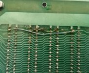
There's a blasted trace on the board between slot 12 and slot 9, I think it's on pin 52, the -16v line. (Which I keep erroneously calling 18 volts, apparently.) Curious how that happened. Whoever fixed it just bridged slot 12 to 9, skipping 11 and 10.

attachment.php
 

Attachments

  • blasted_trace.jpg
    blasted_trace.jpg
    139.5 KB · Views: 4
The +8V cap coming up so fast could mean that it was great and needed little reforming or it could mean it was dry inside and was just an empty can. You'll know more when you put some load on it.
The other two sound like they are making progress. The leakage current is dropping off, as expected. It wouldn't hurt to leave them on for a another day.
The burned out trace would mean something with a dead short on it was across the wires. A tantalum capacitor would have blown off the board with that much current. I noticed that two of the connectors have been bypassed. It is possible something on the board that was plugged in caused a short.
It is suspicious that two of the connectors were bypassed. Normal repair would have put a wire to each. You might check for shorts or broken connector pins in the edge connector. Another place for possible solder bridges is under the connectors.
Many boards don't need these voltages but if there was no other reason to not connect then, I'd put them all wired back in. Check for shorts to all adjacent pins and pins across the connectors. There are 5 possible shorted paths. Check them all before wiring all the connectors back in line.
Dwight
 
The +8V cap coming up so fast could mean that it was great and needed little reforming or it could mean it was dry inside and was just an empty can. You'll know more when you put some load on it.

As of the last reading a little while ago the voltage across the 8v cap's resistor is down to 4.4 volts, which if I'm understanding the instructions here correctly means it's making progress. With a 42kohm resistor on seven volts (I've noticed the voltage from the transformer has been slowly inching up, it could well be I've had low voltage to my house because of this heat) according to ohm's law I'm only charging that monster at a maximum of 0.00019 amps, or 1.5 milliwatts. So I'm hoping that means the cap is fine and it's just taking forever because the allowed current is so conservative. I have some 10k resistors, I suppose I could swap in one of those, but I'm tempted to just leave it as is at least overnight.

The -16v cap is down to only .5v across the resistor. The +16v cap is still at around 2.3v. The negative one is only slightly smaller than the positive, which makes me wonder why its seems to be "reforming" considerably faster, but both are trending the right way.

I was wondering if there might be a solder bridge or something under those connectors, as you said. The soldering quality... is not great, overall.

Speaking of tantalums, as I mentioned there seem to be quite a lot of them. (Mostly in places where I'd expect electrolytics; Wikipedia claims there was some kind of price shock on tantalum around 1980, I wonder if that's the deal.) I've been planning to go through and check to see if any of them look like they're dead shorts before I power it on for the first time, I don't know if that'll save me, though.
 
I see I misunderstood your post I thought you were saying the voltage on the resistor was .6V. you were actually saying it was the voltage on the capacitor.
I see no reason you would want to change the value of the resistor. It sounds like it is doing fine. The larger capacitor should have greater leakage. It sounds like it is getting better. You don't need to rush it. Just let it take some time. The better is forms the better it will work in the long run.
Dwight
 
Last check before bed we're down to 3.8v on 8v, 1.6v on +16v, 0.38 on -16v. Cautiously optimistic that those cans actually have more to give in life, or at least they will after another dozen or two hours of gentle persuasion.
 
Still running the capacitor bake; the big 8v cap is down to about 2v across the resistor, +16v is down to about a volt, -16v is under .2v. So it looks like it's still working, although the rate of improvement seem to be slowing down as capacitor charges. I'm kind of wondering in the case of the big one in particular if there might be a point where 1.5 milliamps is going to equal the self-discharge rate of the cap and it won't be able to charge it anymore with a resistor that big. But as long as it keeps dropping I'm satisfied to leave it. Hasn't plateaued yet.

For such a boring process I did managed to experience a fair bit of drama on Sunday morning, involving having to grab the machine off the patio table I left it on in the middle of the night and move it inside because of an unexpected thunderstorm. Glad my patio umbrella doesn't leak, otherwise things might have gotten exciting/slash/tragic.
 
Yes, it will be an exponential decay curve...

Once it appears the voltage drop (current flow) has fallen off, decrease the value of the resistor (say by a factor of 2) and repeat the process again.

What you want to end up with is the capacitor connected to the dc voltage source without a resistor with the only current flowing being the rated leakage (or thereabouts).

At this point, you should have successfully reformed the capacitors, and a ripple voltage check with an oscilloscope across the terminals of the capacitor should indicate a very low ripple.

Dave
 
I'm with Dave. It sounds like it is reaching its minimal leakage current. Halving the resistors for some time seems in order. The micro amp flowing shouldn't be an issue for these computer caps.
You can use an automotive tail light as a test load, when you think your ready. Incandescent lamps are close to constant current devices, over a wide range of voltages.
 
I'll leave it until morning as is, but it does look like I've hit something of a homeostasis on the +8v cap around 2.2v as of around 5PM. I have enough 42k resistors I can double them up for 21k; I'll see how that moves the needle.
 
Welp, I left the Northstar baking all week; in two steps I reduced the resistance on the +8 cap from 42k down to 14k (the latter resulting in an approximately five milliamp current limit, up from the 1.5ma I started with) and the voltage drop across the resistor is down to under 0.6v. That's looking pretty low, so I guess today I'm going to go ahead and pull the resistors out and try the supply with a small load on it.

I'll probably dip into that box of broken xmas light strings and just cut some series groups for the initial load. (Google tells me the standard for those is 2.4v, so a string of four in should be fine for +8 and twice as many for the other two.) I'll also yank out the oscilloscope and see if I can get an idea of how smooth the output is.
 
So, this morning I took out the resistors and put all the power supply wiring back together. After loading the outputs with this ridiculous dingus I soldered together out of xmas tree bulbs:

xmaslights.jpg

and powering it on I checked it with the oscilloscope, and while I'll admit the scope I'm using is elderly and might miss things so far as I can tell there's no detectible ripple on any of the three voltages, looks like solid DC through a wide range of frequency divisions. When powering off it takes about 20 seconds for the +8v line to drain enough to put the bulbs across it out, the other voltages have 8 bulbs and go dark in a few seconds. (But their caps are also a lot smaller.)

Output voltages in this mostly unloaded state are about +10v, +21v, and -21v. *Slightly* worried that the 16v feeds are a little on the high side but it looks like they're still technically within tolerances, so I'm inclined to say this looks good enough to proceed.
 
Looks good (and pretty) to me!

Heh. After making this I kind of want to make a completely useless peripheral card that just has a couple open-collector latches capable of sinking enough current to drive xmas tree bulbs so I can construct a genuinely old-tyme incandescent blinkenlights panel.

That said, soldering rusty tree bulb leads is a chore. Bleah.
 
Okay, I've reinstalled the backplane and wired it up. (Technically I think it wants more cleaning, but I got enough of the snot off it I think it's "okay" electrically.) Taking voltages off some random points, I see a reasonable approximation of 5v on the VCC lines of the chips in the onboard peripheral area, also seeing +5v on the appropriate lines of the floppy plugs, but on one floppy plug I'm getting +12v where I should while the other is showing 20v. Digging out the manual, but off the top of heads, does this board have a separate regulator for each floppy connector?

I hope it wasn't powered up with a bad regulator on one of the floppies and smoked one of the SA400s...

Edit: On the good news side of the equation probing the serial port voltages confirms that the +12/-12v regulators used by the backplane logic are good, so so far it's just the one floppy connector. According to the supplementary manual I've started with a passing reference to the main kit assembly instructions implies there are separate regulator components for each floppy drive, so, more digging.
 
Last edited:
If it’s anything like the Cromemco, they have separate voltage regulators for each drive. When I powered up my Cromemco, I did check the floppy regulators out without the drives connected, and did find a shorted regulator. Had I had the drive connected I probably would have fried it...

A PDP-8/e was used to drive someone’s Christmas tree lights, so you have been beaten to that :)!

Dave
 
Part of me is tempted to tuck a more modern supply into the case somewhere to run the floppy drives, but I suppose I should fix it right. :)

I really wish this turkey had a monitor ROM so I could probe it further for life without worrying about the disk subsystem. I guess I should add the parts to add a ROM to the CPU card to the shopping list.
 
Adding the PROM monitor on the Horizon CPU board is a lifesaver when it comes to getting the machine up and running. Very simple to do with a 2716 or 2732 (as a 2716) versus the 2708 it was designed for. See https://deramp.com/downloads/north_star/horizon/roms/ZPB-A PROM Mod.pdf.

Since I'm stalled for a bit on a dead voltage regulator I was going over the instructions for this modification with the CPU board and manual in hand. (And realizing the board has the same gross flux problem as on the back as the motherboard, so it's going to get a wash, but that's neither here nor there.) Looking at everything I was just curious about something; is there a reason why the PROM mod entails adding a (currently unpopulated) pull-up resistor network on A0-A9 between the Z-80 and the PROM socket? (And since the mod also routes A10 to the PROM socket does it need to have a pull up added as well?)

Basically I'm wondering if this pull-up is something that was specifically needed because of some badness with the 2708 and if it wouldn't be necessary on a more modern part. I've been comparing pinouts and I'm kind of tempted to cobble up an adapter using a machine pin socket to put an SST39SF010A flash chip (because I have an ample supply on hand). Looks like there's *just* enough clearance around the 24 pin socket for the overhang from the 32 pin chip, and everything pretty much lines up otherwise. (Just need to tie the unused address pins to ground and route VCC to pin 32 hanging out there in space.)
 
I would say you certainly don’t need the pull-up resistors on the address bus with a 2716 / modern device.

I would have to check out the other resistor a bit more carefully, but (on first look) that one isn’t required either.

Dave
 
I would have to check out the other resistor a bit more carefully, but (on first look) that one isn’t required either.

Do you mean R4, 3.9k? Yeah, I assume that's only there because the resistor network they used wasn't long enough. (ZA0-ZA8 are on RN3, ZA9 is on R4.)

If I didn't need the resistor network then the most BOfA idea I have for making the flash go is dead-bugging a GAL onto ZA11-A15 at the sockets for the LS136s and using it to generate the regular and inverted PROM-SEL signals, then I'd pretty much have everything on hand I need, but maybe that's going a bit far to avoid waiting for a mail order delivery.

In other news, while washing the CPU and floppy boards I discovered at some point the +16v trace (pin 2) on the FDC got completely evaporated between the slot pad and the first tantalum capacitor. (Subsequently fixed, kind of messily.) S-100 machines lead hard lives.

boom_fdc_trace.jpg

There's also a number of patch wires on the back of the FDC board, should probably try to figure out what they're for.
 
Back
Top