WARNING: Lots of text and images
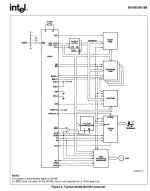
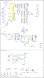
Hello. In my last post about my 80188 Computer project, called the SeaOtter Essentials Prototyping computer I talked about details of the computer itself. However, I wasn't happy about the Layout of all of the components on the PCB and the size of the PCB. It all felt a little too big. So I spent some time to create a smaller PCB with a neater and better component layout. The first board design only had 4 PCB layers, this new design has 8 PCB layers. Here are the results of my hard work and effort:
 + Length and Width Measurements")


.png")
I am very proud of the improved PCB design I've created. This design to me looks more organized and pleasing to look at. Now, as for my response to the post I've created before this one, I've decided to use 74HCT series logic chips because of their TTL compatibility and low current consumption. However, when I add a serial and an I/O Controller, I'll upgrade to either 74ABT or 74BCT because those logic chip series are designed for driving system busses and have a high current capability that's TTL compatible, which will be useful for when I need to add the Bus Transceiver ICs to separate the Data Bus from the multiplexed AD0-7 pins. I do apologize for not making my concerns over what Logic Chip series clear. I was mainly concerned with the fact that Address Line A0 is branched between the Keyboard Controller, VDP and an LCD Screen I'll use for debugging. I've found all of the Part I need from DigiKey and I'll leave a list below:
Now, All but one of these parts are labeled "SN74HCT___N", except for the 74HCT21, which as you readers can see has "CD" before the model number and "E" at the end. Does that mean I can't use the CD74HCT21E because its not a "SN74HCT___N" labeled chip, or does the "SN74HCT___N" and "CD74HCT___E" parts of the model number mean nothing and the only thing that matters is the fact that it's still a 74HCT series chip? (I'm sorry if this is an extremally stupid question to ask)
However, Before I'll order this new PCB, I'll need to test everything out on breadboards. I've made a 80188 breakout board in EasyEDA. I'll show the design in a reply to this post because Posts have a 10 image limit. Also in that reply, I'll show pictures of the hardware I've collected for this project.
As always, Thank you guys for reading and if any of you guys have any advice for me, It'll be thanked in advance!


 TMS9918A Video Display Processor (Bottom)")