• Please review our updated Terms and Rules here

My project: The SeaOtter Essentials Prototyping Computer

Also, you might get more bang for the buck by substituting the 80C188EB processor. Lots of nice stuff there and readily available. The 80C188EC is even better, but you don't get it in PLCC--it's available only in 100-pin QFP.
 
Also, you might get more bang for the buck by substituting the 80C188EB processor. Lots of nice stuff there and readily available. The 80C188EC is even better, but you don't get it in PLCC--it's available only in 100-pin QFP.
We have already gone through the same comments with the OP in a separate thread regarding the choice of CPU.

Dave
 
Also, you might get more bang for the buck by substituting the 80C188EB processor. Lots of nice stuff there and readily available. The 80C188EC is even better, but you don't get it in PLCC--it's available only in 100-pin QFP.
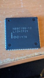
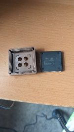
I already have a PLCC-68 80C188. It's just the standard version, which is what I want to use. I'll upgrade to the better versions in the future of this project
 

Attachments

  • PXL_20230804_001009822.jpg
    PXL_20230804_001009822.jpg
    1.2 MB · Views: 0
  • PXL_20230806_154102898.jpg
    PXL_20230806_154102898.jpg
    1.9 MB · Views: 0
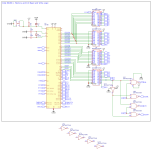
I was told that for a small 80188 computer, I don't need to use the bus transceivers for the Data Bus. The datasheet for the CPU shows a typical computer setup diagram of which I'll show in this reply.

Okay, it’s a “small 80188 computer”, I‘d agree with that… until you started bellyaching about how you needed all this massive drive strength for the address lines because of the bazillions of peripherals you were going to add to it. (That you’re setting the threshold for “bazillions“ comically low is another matter.) Which is it, is this a “small computer” or not? If your handwave for this is you can just add a data bus transceiver later, here’s my responses:

A: you’ve already broken a general design guide no-no by running that unbuffered segment through an external connector; even if you tack a bus transceiver onto your expansions you’ve put a source of potential noise on the wrong side of it.

B: you need some logic to set the direction/enable for this part, it makes way more sense to build that now and get it over with, integrated onboard, and,

C: if this is your attitude, that it’s a small computer and if signal integrity is something you’ll worry about later, then why wouldn’t you also just say ”eh, I can always slap a line of ‘244s on my card if I need to reset address bus fanout” instead of wasting all this ink asking about what Hercules strength parts to use for your apparently *intentionally* half-baked bus now?

This is why I’m kind of wondering about that trolling theory. At the very least it seems like every discussion about this thing turns into schizoid ping-ponging between whether the goal you’re building towards is a desktop computer or a wall-size MultiBus monster, and at random you seem to completely conflate the requirements for the former with the latter… except where you don’t and decide you’re building an embedded SBC.
I'll just say this. I'm not trolling. This is a new hobby for me and there is still a lot for me to learn about building a computer like this. I apologize for my unprofessional behavior. I know what I want to build stemming off of this prototype. I was just paranoid about the parts that glue this project together, the Logic Chips. I'll fix the pin headers for the Data Bus in the next board design that'll be based on the new advice given to me in this post.

I cant thank u enough for all of the advice you and others have given me.
 
I'll fix the pin headers for the Data Bus in the next board design that'll be based on the new advice given to me in this post.

Here's the schematic for a Commodore PET that is *kind* of doing what this amounts to; the address signals are buffered and go *everywhere*, IE, to all the onboard stuff *and* the bus connector, while the data bus is only *partially* buffered; the "raw" version goes to the three I/O chips and the ROM... but the buffered version goes to both the onboard RAM and the bus controller. But, again, note that the buffer is indeed *before* the bus connector... and, also, if you look at the RAM schematic there's a buffer there too. In other words, this part of the Commodore PET looks just like the IBM PC, IE, you have onboard devices essentially at the same "buffering level" as a well-designed expansion card on a bus segment where the CPU is the master.

FWIW, this is another general comment about your design: I don't understand why, if you're intending to build extensions for this thing, you've randomly terminated your bus signals onto randomly placed groups of pin rows. What is the point of this? It would make far more sense to bundle these signals into bus connectors that would let you either direct-plug daughter boards or plug in standard IDC dual-row ribbon cables.

I think I suggested this before, but I'll lay it out again: In my humble opinion, in addition to buffering the data lines with a '245 before hitting a bus connector, you should be latching the S0-S2 signals on the same '573s you're putting A16-A19 on, and adding a little bit of logic to generate separate I/O and memory read/write signals as detailed on page 3-5 of this 80188 manual. Doing this will essentially give the signals you need for an ISA-compatible bus subset, and you will kind of need it anyway if you ever want to interface anything to this thing using "discrete" address decoders instead of the U/L/M/P/CS lines. (Which I notice you're running to their own pin headers... even the ones you've already used for onboard peripherals? Not sure what the point of that is.)

Arrange these signals appropriately on a 62+ pin dual row connector and you'd be able to drive simple ISA cards with nothing but a passive backplane board plugged in to convert those pin signals into slots. I would need to read a bit more/scratch my head for a while, but I think you might even be able to run the 80188's INT pins to the some of the interrupt pins on the bus connector (You have four, I would probably suggest mapping those to PC INTs 2, 3, 4, and 7, maybe?) and be able to handle PC adapter boards that require interrupts, like serial controllers. (* obviously you're writing all your own software to do this) You should even be able to drive devices like PC video cards as long as there isn't a memory conflict with your onboard RAM.

Even if you insist against ever putting an ISA slot onto your machine for religious reasons adding the separated R/W signal generation now will make it a lot easier for you to copy existing homebrew designs for your add-on hardware. I mean, if nothing else it is worth noting that you are essentially already out of built-in memory select signals on the 80188; you have a few more PCS signals for I/O mapped hardware, but they'll go fast once you start adding serial ports and mass storage controllers.

Also, I'm sorry, you can't be serious about an 8-layer PCB board. Where are you planning to buy this?
 
Last edited:
Maybe times have changed a lot in 3 decades, but multi-layer (other than, say, 4) boards were a PITA to QA and debug. The reject rate on them used to be pretty high, mostly due to registration problems. And they were EXPENSIVE.
 
4 layer boards aren't too expensive nowadays, but 6+ layers are considerably more. Also with 4 layers you have a reasonable chance that mistakes can be fixed with a cut and strap.
If I was designing this I'd probably go with 4 layers. One inner layer for 0V, the other inner layer for power distribution and short tracks where absolutely necessary. The outer layers for the majority of the tracking one predominantly vertical and the other horizontal.
 
4 layer boards aren't too expensive nowadays, but 6+ layers are considerably more. Also with 4 layers you have a reasonable chance that mistakes can be fixed with a cut and strap.

For laughs I took a look at JLCPCB (about as cheap of a PCB mill as you'll find), and I guess my two observations are:

A: 4-layer boards suddenly seem to be a lot cheaper than they were the last time I made a PCB board? I've been too busy with real life to do one for, I dunno, a couple of years. If they were as cheap then as they are now I probably would have used one instead of torturing myself with getting my last project onto a 2-layer board, but...

B: A six layer board starts at literally almost an order of magnitude more than a 4 layer board. I didn't bother trying to find out how much an eight layer would cost.

I hadn't looked at the OP's layer breakdown pictures before now, and... no, just no. Some of the layers literally have like a dozen tracks on them at most. This would be incredibly wasteful even if it was a complex board with tiny-pitch surface mount parts, but this is through-hole. Doing it two layers would be very doable, and four layers should be "easy" even for a novice.

I guess I'll chuck this out there; it's the fourth PCB I ever routed. By hand. It's two layers, and it works. I'm not going to soft-pedal it, routing it was kind of a nightmare that involved a lot of non-linear thinking and a shedload of vias, but that's mostly because of the size constraints. (This had to fit into the available board area in a Tandy 1000 EX/HX, which is only about the size of a standard US postcard.) If it's not *quite* possible to fit this 80188 computer onto a PCB roughly the size they have for their 8-layer board in two layers it's *definitely* possible in four, and I don't think you'd need to be a miracle worker when it comes to routing to do it.

crazyrouting.png
 
If I was this uncertain about an unproven design, I wouldn't start with PCB. I'm old-school--I'd do a wire-wrap version first.

For two layer boards the far east PCB mills are so cheap it might be more economical to just do a best crack at it and hack with bodge wires, unless you really blow it.
 
Well, my take is if you're wandering around in terra incognita, wire-wrap is a lot easier to bodge than soldering wires and cutting tracks. I'll confess to having done the latter, but the changes were mostly minor (e.g. changing a level-triggered flipflop to an edge-triggered configuration). On multilayer PCBs, this can get to be pretty challenging.
 
Maybe a hybrid approach would be to do a PCB with the "known knowns" routed-- +5 and earth and potentially things like "connect all the RAM/ROM low-address and data lines" and then solder on sockets with long pins. Wire-wrap the rest-- controls and chip selects-- to the "long pins"

A PCB can avoid some likely cockpit errors when wire-wrapping (off-by-one-pin, missing one pin, accidental shorts of exposed wire ends, components popping loose), so using it for the parts of the circuit you're already 100% confident in might work, if you don't mind the cost and delay of ordering a PCB. It also reduces a lot of the tedium factor of cutting and placing a hundred or so wires.

I will join the chorus that 8 layers seems a bit excessive, considering, for example, the Xi8088 design is only two layer and it's got a lot more discrete ICs to deal with. It might make sense to build a "comparatively" sparse board for early testing, where you expect to spend a lot of time poking probes and pulling chips from sockets, then once you have the schematic down pat, shrink it down to use space more effectively.

Personally, I'd also propose if you're going to expose so much of the processor signals, you might want to think about arranging it more like an expansion slot for future use. It makes me think of a lot of old home computers that just mapped anything interesting from the system bus on the cartridge/expansion slot. A 2xN 2.54mm pitch connector would allow attachment of individual pins for debugging, or a daughterboard or ribbon cable for future expansion.
 
Hello everyone who read this post. I'd like to apologize for my unprofessional behavior in my previous posts and replies and to talk about exactly what I want out of my Project.

Here's some details about my project and what I want:
  • The Pin Headers in my PCB design are for jumper cables to go to breadboards with new hardware. The successful hardware tests would've been apart of the next PCB design. (Now Outdated)
  • I don't want expansion slots (More about this later)
  • I've chosen to use 74ACT series Logic Chips due to their Bus Driving capabilities
  • Similarly to the Tandy 100, there will be Data Bus Buffers for Memory (MD) and I/O (IOD) and Address Buffers for Memory and and I/O (AB)
  • I want this computer to be a SBC inside of a case that has the keyboard and monitor built in
  • I've been thinking about this project too fast. I need to slow down before making any big decisions

As for the Expansions slots, the user Eudimorphodon replied in my previous post with a lot of useful information and help for my project. After reading a bit of the 80186 Processor Family Hardware Manual, I learned how to make Memory and I/O Read and Write signals and I've decided I'll make Bus Connectors for the Memory and I/O Busses. After some thinking, My computer project will be similar to a Commodore Pet, if it had color graphics (and I'm using an Intel CPU but that difference is obvious) and the Tandy 1000.

As always, thank you guys for reading!

Here's the schematic I've made for this new prototype design so far.
 

Attachments

  • Schematic_SO Prototype computer_2023-08-25.png
    Schematic_SO Prototype computer_2023-08-25.png
    448.2 KB · Views: 5
Hello Readers! I recommend reading my last post before you read this one.

Still Taking the advice I've gotten my previous post, I've made this schematic!
Schematic_SO Prototype computer_2023-08-26.png

Here are the new additions:
  • The Data Bus has Bus Transceivers for I/O (IOD0-7) and Memory (MD0-7)
  • The Address Bus has Buffers for I/O and RAM similar to the original Tandy 1000 (I was studying the schematics for it)
  • I/O and Memory Read and Write Signal generation
  • The Data Bus Transceivers for Memory and I/O DIR pins are wired to the MEMR an IOR (Again, the Tandy 1000 did this)
I only have one minor concern. The Bus Transceiver (U18) that's used for the Memory doesn't have logic for the OE, so I just put it to GND. Is that a problem?

As always, if you guys see any more errors or mistakes, please let me know in the comments below! Any help and advice is thanked in advance!
 
I only have one minor concern. The Bus Transceiver (U18) that's used for the Memory doesn't have logic for the OE, so I just put it to GND. Is that a problem?

Yeah, that’s not really great. A better idea would be to AND together all the chip selects that are behind it so it’s only enabled when one of them is. Otherwise this is going to drive the bus and ruin your day if you interface a memory device to your expansion bus.
 
Yeah, that’s not really great. A better idea would be to AND together all the chip selects that are behind it so it’s only enabled when one of them is. Otherwise this is going to drive the bus and ruin your day if you interface a memory device to your expansion bus.
I knew it! Thank you so so much!
 
Back
Top