• Please review our updated Terms and Rules here

Neglected PET needing some love

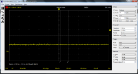
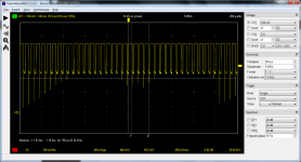
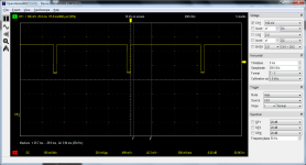
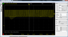
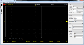
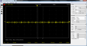
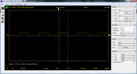
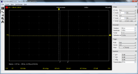
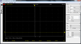
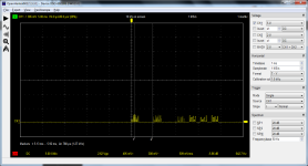
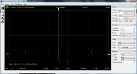
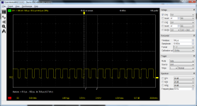
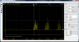
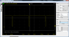
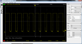
Well the sync pulses on B and D look ok despite the fact that the H drive signal from the PET on point A looks very abnormal and appears to have some interference modulating it.

The V drive from the PET on C looks normal.

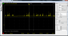
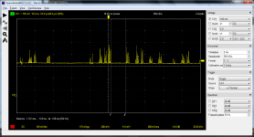
The video signal from the PET looks far too low in level, unless the scope is simply missing its peaks on samples. Can you fill the screen with a checkerboard like pattern of characters or symbols to get a solid video signal.

The terminated sync pulse voltage is a tad high, but that is easily fixed. Ideally the sync terminated should be around 300mV and the video signal rising 700mV above that to end up with 1V pp.

The first thing to find out is why the H drive signal from the PET looks so abnormal and why the video pulses look so low in level, that is likely just the scope settings I think.

On the recording A where was the trace (zero voltage line) before you connected the probe ?
 
Last edited:
This is most confusing.

I don't understand where the 'negative sinewave imprint' is coming from.

Can I suggest disconnecting the new adapter board from J7 on the PET and then measuring the H DRIVE signal with your oscilloscope. Whilst you are at it, can you measure the V DRIVE and VIDEO signal as well?

Let's reduce the problem to the PET first.

Then connect the adapter board and re-measure the same signals again to look for differences.

Make sure you use the same oscilloscope settings for the measurements both before connecting the adapter board and after connecting the adapter board.

Dave
 
Getting a good pattern on the screen is going to be a bit tricky since I can't really see what's going on without moving my rgb2hdmi down into the basement which would involve a lot of unrunning wires from behind a desk and monitors and stuff, which I can do but to be lazy for now I just connected this adapter back up to the apple monitor /// and kept hitting some keys, I can see something filling up the screen.
side note seems my keyboard repair may not have held some of the keys are being non-responsive again.
anyway here's the video signal, I'm not sure I notice much difference:
1676381287695.png
 
There is something wrong with the signals you are measuring - either from the PET or using the oscilloscope.

All of the signals from the PET (H DRIVE, V DRIVE and VIDEO) should be 5V TTL signals. I don't see this on your oscilloscope traces.

In addition, the video signal may be suffering from poor sampling.

We need to get the measurement technique sorted out first before we move on to the adapter.

First, can we work out where the 5V signals have gone to? Do you have a x10 probe in circuit for example - meaning that the signal that is displayed on the oscilloscope should be ten times the indicated value.

Dave
 
just to make sure I was looking at where I was getting 5v from, which is from one of the 74ls5157's I had replaced earlier.
I checked with a multimeter, it's 5v as expected.
then, on the scope, with the probe set to 1x it shows as 5.13v, and with the probe on 10x is shows as ~595mV

So, to recap, all of the measurements prior have been done with the probe set to 1x (except for the one in my last reply, #368)
 
So, the post in #368 indicates 632 mVpp with a x10 probe - so we have a peak-peak level of 6.32 Volts Is that correct?

I suspect some of that is undershoot though.

So, where is the 0V/GND level on the oscilloscope? Can you set the probe input to GND and adjust the Y-position until the horizontal oscilloscope line aligns with one of the major division lines - allowing for some signal undershoot (i.e. not the very bottom of the screen).

It is very important to always know where the GND reference is on the oscilloscope display.

Dave
 
Do you mean connect the probe to the ground pin on J7? And leave the ground connector of the probe disconnected?
Well let me try a few things:

First, setting the probe back to 1x. Here is the probe not connected to anything:
1676385132154.png

Here is the probe connected to the ground pin of J7 (the ground of the probe not connected to anything), the PET is off:
1676385177137.png

and for reference here is the probe connected to the 1khz test signal on the hantek (and the adjacent ground connector):
(time base increased to 500us)
1676385266833.png
 
No...

You ALWAYS need your ground probe connected from the oscilloscope to the PET.

If you look on either the probe - or your oscilloscope - for the Y channel you should see the settings AC, DC, GND. I would (personally) do it on the oscilloscope.

Set the Y-channel to GND and you should get a horizontal line. Adjust the level to be one major division up from the bottom of the screen. This is our GND reference. Then, switch the channel back to DC and take the signal measurement.

In my opinion, use the x1 probe setting every time (to save confusion) if you can. You only need to use the x10 setting for sensitive or very low current electronics (e.g. measuring on crystal oscillator pins or timing circuits).

Does this make sense?

Dave
 
I see what you're saying but I assumed that would be under that dropdown in the top/right that is currently set to "DC". unfortunately when I click that "DC" is the only option.
 
Of course, this is not a 'real' oscilloscope is it...

You should (however) have at least AC and DC on the dropdown.

If not, no problem, disconnect the probe from the PET and clip it to the same point as the GND from the oscilloscope.

Failing that, my oscilloscope probes have a x1, x10 and GND switch. However, yours may not have the GND setting.

Just connect the probe tip of the oscilloscope to the GND clip of the oscilloscope.

Dave
 
So it is in the middle?

Is the yellow arrow thing on the right-hand side the trigger level or the Y position?

Can you shift the line up and down with some control?

Dave
 
Last edited:
Excellent.

So that has got our 0V/GND reference correct now.

Why have you returned to 5V/major division with (I assume) a x1 probe? We now get a tiny signal indicated. Can you revert back to 1V/major division.

H DRIVE and V DRIVE will probably look OK then. But we will need to work on the VIDEO signal.

Dave
 
I think on that software you can actually 'left mouse hold-and-drag' the markers / cursors at the side of the display.

Edit: The discussion has moved on some way since I started to type my post, then got distracted...
 
okay 1v per division
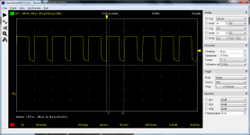
Here's the video. I'm not sure what timebase would be best but this seems reasonable just given the waveform that's showing at the moment:
1676394817652.png

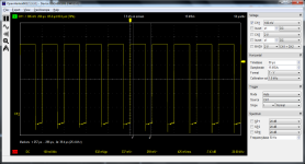
Here's the vertical again:
1676394859522.png

And horizontal:
1676394897526.png


I keep trying to blind-type in a simple screen filler like:
10 print "X";
20 goto 10
run

but I think there's enough keys not working well enough that it never seems to work. I may have to drag my rgb2hdmi down to the basement just so I can see what I'm typing.
 
Back
Top