Upcoming Events:
| VCF West | Aug 01 - 02 2025, | CHM, Mountain View, CA |
| VCF Midwest | Sep 13 - 14 2025, | Schaumburg, IL |
| VCF Montreal | Jan 24 - 25, 2026, | RMC Saint Jean, Montreal, Canada |
| VCF SoCal | Feb 14 - 15, 2026, | Hotel Fera, Orange CA |
| VCF Southwest | May 29 - 31, 2026, | Westin Dallas Fort Worth Airport |
| VCF Southeast | June, 2026 | Atlanta, GA |
-
Please review our updated Terms and Rules here
You are using an out of date browser. It may not display this or other websites correctly.
You should upgrade or use an alternative browser.
You should upgrade or use an alternative browser.
Neglected PET needing some love
- Thread starter Divarin
- Start date
daver2
10k Member
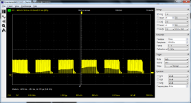
So the VDRIVE and HDRIVE signals look good.
Please note the X and Y settings for use with your adapter...
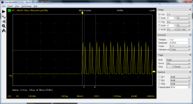
Can I ask you to do one more trace of the H DRIVE signal at the same timebase (X) setting as used in post #366. Please keep the Y setting (Voltage) the same. I would like to see if the weird sinewave artefact is still there or not.
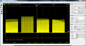
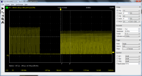
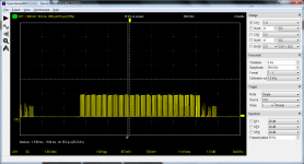
The VIDEO signal is awful I am afraid. We need to work on the timebase. The video signal is also a TTL signal - so should also be swinging between 0V and +5V - but I suspect that there are not enough samples to resolve the signal. We will play with that shortly...
Dave
daver2
10k Member
I see you posted in between mine.
That looks more promising. Your oscilloscope still doesn't have the resolution to 'see' the video signal accurately, but we may be able to work around that.
Can you still take my H DRIVE trace as I asked for in my last post please?
Dave
That looks more promising. Your oscilloscope still doesn't have the resolution to 'see' the video signal accurately, but we may be able to work around that.
Can you still take my H DRIVE trace as I asked for in my last post please?
Dave
Divarin
Veteran Member
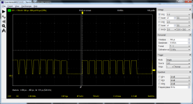
Ok so that's a timebase of 500µs:So the VDRIVE and HDRIVE signals look good.
Please note the X and Y settings for use with your adapter...
Can I ask you to do one more trace of the H DRIVE signal at the same timebase (X) setting as used in post #366. Please keep the Y setting (Voltage) the same. I would like to see if the weird sinewave artefact is still there or not.
The VIDEO signal is awful I am afraid. We need to work on the timebase. The video signal is also a TTL signal - so should also be swinging between 0V and +5V - but I suspect that there are not enough samples to resolve the signal. We will play with that shortly...
Dave
daver2
10k Member
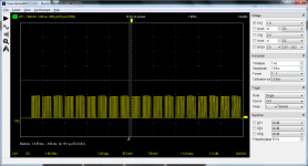
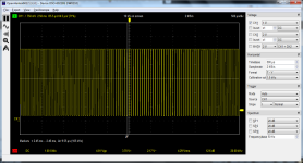
So, that is good. None of the strange artefacts appearing (as it should be).
I think the problem with your video signal is that you are not sampling fast enough to observe the detail. As a result, the oscilloscope is capturing the video signal at too long an interval and you are getting aliasing effects. This is where you do not observe the 'correct' waveform (as presented to the oscilloscope) but what is effectively a 'beat frequency' between the original signal and the sampling rate.
You need to find a fast enough sampling rate over a short period of time to resolve the video signal details.
However, in order for the signal to be stationary on the oscilloscope, you will need to use the second oscilloscope channel to act as a timebase synchronisation signal.
Have a 'play' and see what you can come up with.
Dave
Hugo Holden
Veteran Member
That is a strange sine wave artifact on the video signal.
Perhaps when the scope settings are finalized to be able to see the video signal better, if you have any other source of a video signal to try, say from a DVD player or some other source might help to check if the scope is set up right. One problem is that the video signals from the computer text are very fine pulses of short duration, could be in the very rough 100nS vicinity for a single dot/pixel that makes up the text symbol and if the sample rate is too low in a digital scope, they simply disappear from the trace. The H & V sync pulses are much wider being around 5uS for the H sync and maybe 3 x 50uS in this case for the V sync so the scope has no trouble with them. To see the video signal properly, the scope ideally would have at least a 10 to 20MHz effective bandwidth (if it were analog), or easily resolve an 8 MHz signal.That likely means, for a digital scope, the sample rate would have to be at least double that (Nyquist 2f) to be able to reconstruct the waveform for display.
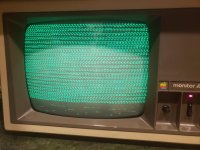
Regardless of the scope settings/issues, I think, from what I have seen, that the adapter board is likely working and there are both H & V sync at the adapter's output, and some video signal too. And for some reason, your VDU could not lock to the 20kHz H sync rate, but had locked to the vertical sync, and there was video information in the image on the CRT face. So if you could get the VDU to come into H lock, it could be easier to see what is going on that way.
daver2
10k Member
The video shift register is fed from a 16 MHz clock source.
Converting this to a period gives me 0.0625 microseconds (us) = 62.5 picoseconds (ps) per dot.
So this is what we are talking about resolving with your oscilloscope.
You could also clip your oscilloscope onto the PET's CLK16 signal (16 MHz) and seeing if you can resolve this adequately on your oscilloscope. For an 8032 this would be UA2 (74166) pin 7.
Could I suggest looking in the specifications for your oscilloscope to see if it will be capable of resolving this or not.
Dave
Divarin
Veteran Member
Okay I've kind of run out of time to play with it anymore today.
Aside from the scope issues, I did try connecting the composite output to an LCD monitor as well but it wasn't able to lock onto a signal, but that might be the case even if it is a proper signal that the Apple monitor /// will take.
As for adjusting the horizontal pulse shortener does it seem reasonable to try adjusting the resistance value of R1 (what is now 10k ohm) and see what effect that has on the picture?
Hugo Holden
Veteran Member
nS I think. To see individual dots, where you turn adjacent pixels on & off, or clock out a high, then clock out a low, then a high, etc at 16MHz, the pixel will be on for the period = 62.5 nS (I said very roughly 100nS)The video shift register is fed from a 16 MHz clock source.
Converting this to a period gives me 0.0625 microseconds (us) = 62.5 picoseconds (ps) per dot.
Dave
Hugo Holden
Veteran Member
I think the sync pulse widths are ok, and I cannot see any reason to adjust those yet. It is a matter of getting the horizontal scan circuits in the VDU to run at close to 20 kHz so it can lock. Do you have aVDU that can definitely run at that rate ? Or maybe can the CRTC be reconfigured for the approx 15.7 kHz rate ??Okay I've kind of run out of time to play with it anymore today.
Aside from the scope issues, I did try connecting the composite output to an LCD monitor as well but it wasn't able to lock onto a signal, but that might be the case even if it is a proper signal that the Apple monitor /// will take.
As for adjusting the horizontal pulse shortener does it seem reasonable to try adjusting the resistance value of R1 (what is now 10k ohm) and see what effect that has on the picture?
Divarin
Veteran Member
Hmm I don't know I have other monitors I can use that take composite inputs but what h.sync frequencies they'll accept I don't know.I think the sync pulse widths are ok, and I cannot see any reason to adjust those yet. It is a matter of getting the horizontal scan circuits in the VDU to run at close to 20 kHz so it can lock. Do you have aVDU that can definitely run at that rate ? Or maybe can the CRTC be reconfigured for the approx 15.7 kHz rate ??
I'm not sure how I'd reconfigure the CRTC, I'd assume that would involve some pokes?
Hugo Holden
Veteran Member
I'm not sure either. My PET does not have the CRTC IC, but in theory it should be possible.Hmm I don't know I have other monitors I can use that take composite inputs but what h.sync frequencies they'll accept I don't know.
I'm not sure how I'd reconfigure the CRTC, I'd assume that would involve some pokes?
SiriusHardware
Veteran Member
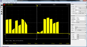
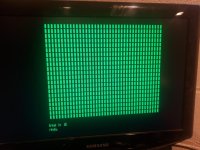
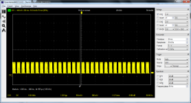
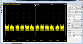
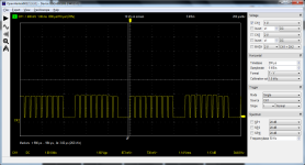
Does the PET have some printable graphics characters that you can try filling the screen with, difficulties with the keyboard notwithstanding? If you can fill the screen with alternating [white character block' + space], that will draw a screen full of white (or green) vertical lines which are much thicker than the minimum pixel dot width - or - just fill the screen entirely with white blocks so that one video line will consist of sync + a full line of peak white.
Hugo Holden
Veteran Member
I agree, that is what I suggested in post #361, to try to get a solid video signal for scope viewing. But not being able to see what you are doing on a VDU screen in the first place, could make it difficult initially, unless somebody could make a small BASIC program to do it. Maybe we need to have a small BASIC "Test Pattern" on file.Does the PET have some printable graphics characters that you can try filling the screen with, difficulties with the keyboard notwithstanding? If you can fill the screen with alternating [white character block' + space], that will draw a screen full of white (or green) vertical lines which are much thicker than the minimum pixel dot width - or - just fill the screen entirely with white blocks so that one video line will consist of sync + a full line of peak white.
Divarin
Veteran Member
SiriusHardware
Veteran Member
Those chunky blocks will provide wider 'blips' on the video signal for your scope to look at.
Divarin
Veteran Member
Hmm strange, on pin 7 of UA2 I can get a reading of anywhere from 8khz to 8mhz depending on what timebase I'm using but not 16mhzThe video shift register is fed from a 16 MHz clock source.
Converting this to a period gives me 0.0625 microseconds (us) = 62.5 picoseconds (ps) per dot.
So this is what we are talking about resolving with your oscilloscope.
You could also clip your oscilloscope onto the PET's CLK16 signal (16 MHz) and seeing if you can resolve this adequately on your oscilloscope. For an 8032 this would be UA2 (74166) pin 7.
Could I suggest looking in the specifications for your oscilloscope to see if it will be capable of resolving this or not.
Dave
Divarin
Veteran Member
Hugo Holden
Veteran Member
Post #395 simply shows that the Apple VDU has not horizontally locked. (I'm not sure about the scope recordings of the video) , but going by what I can see on the Apple VDU face, I think it would look normal if it went into H scan lock and from what I have seen on the scope recordings so far, the H and V syncs coming out of the adapter are perfectly fine. Notice how the components of the "break in 10 Ready" message, at the bottom of the picture on the Apple VDU look very sharp & clean & highly detailed, even though scrambled, due to no H lock. This indicates that the video signal component of the composite signal coming out of the adapter is perfectly fine too. And the V sync is good as that has locked fine and there is no rolling.So I am fairly confident, looking at that VDU image, the adapter is working properly. In a sense the Apple VDU is making a better assessment of the signal than we are getting from the scope.
If you could post the circuit of the Apple VDU, I could explain how to get its H scan osc to lock to the 20kHz H sync. A switch will need to be added to the VDU to change its scan rate between the two standards.
If you could post the circuit of the Apple VDU, I could explain how to get its H scan osc to lock to the 20kHz H sync. A switch will need to be added to the VDU to change its scan rate between the two standards.
Last edited:
Divarin
Veteran Member
Hmm I don't really have any details about the apple monitor.
Is there any way to modify the adapter to put out a signal the apple monitor would lock onto currently? I've also tried connecting the adapter to a few other sets and they all look the same. That is the ones that don't just show a "no signal" message.
I was kind of hoping for an adapter that would produce a composite signal that would work on just about anything with a composite input rather than having to modify the monitor to conform with the adapter.

