| VCF West | Aug 01 - 02 2025, | CHM, Mountain View, CA |
| VCF Midwest | Sep 13 - 14 2025, | Schaumburg, IL |
| VCF Montreal | Jan 24 - 25, 2026, | RMC Saint Jean, Montreal, Canada |
| VCF SoCal | Feb 14 - 15, 2026, | Hotel Fera, Orange CA |
| VCF Southwest | May 29 - 31, 2026, | Westin Dallas Fort Worth Airport |
| VCF Southeast | June, 2026 | Atlanta, GA |
-
Please review our updated Terms and Rules here
You are using an out of date browser. It may not display this or other websites correctly.
You should upgrade or use an alternative browser.
You should upgrade or use an alternative browser.
Old eprom programmer help.
- Thread starter samib71
- Start date
daver2
10k Member
No problem.
Have a good evening.
Dave
Have a good evening.
Dave
daver2
10k Member
Is this with the reset button or not?
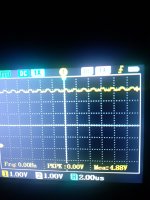
Have you tried setting the oscilloscope up for "single shot"?
You also need to set the oscilloscope to trigger on a HIGH to LOW transition, rather than the LOW to HIGH transition as you currently have.
Dave
Have you tried setting the oscilloscope up for "single shot"?
You also need to set the oscilloscope to trigger on a HIGH to LOW transition, rather than the LOW to HIGH transition as you currently have.
Dave
I soldered a button between c5 terminals i did what you said , i powered the programmer then i pressed the button nothing happened, now i can feel the z80 is getting very hot and there is no clock signal on it all pins have no signal i think the z80 is dead.even the display doesnt change values as before.
daver2
10k Member
Strange...
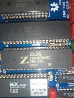
Can you double check where the two terminals of C5 are wired to please.
One terminal should be connected to ground/0V (the negative side of the polarised capacitor) and the positive side of the capacitor should be connected to pin 26 of the Z80.
The Z80 shouldn't have got warm at all either as a result of connecting the button across it, as long as C5 was wired between pin 26 of the Z80 and 0V of course.
Dave
Last edited:
daver2
10k Member
All of the I/O devices (buzzer, display, keyboard etc.) are located within the I/O space of the Z80 microprocessor.
They are all dependent upon qualification by the /IORQ signal.
No /IORQ signal from the Z80, then no I/O devices work. As simple as...
This is why I am concentrating on the Z80's /IORQ signal...
1. There may be no activity at all following a reset.
2. There may be a little bit of activity after a reset, and then nothing at all.
3. There may be continuous activity.
I think we have demonstrated conclusively that point 3 is not the case.
We now need to work out whether point 1 or 2 is the observed result. But, to do this, we need a consistent reset signal (hence the pushbutton across C5). By the way, a faulty C5 (either open circuit or short circuit) couldn't have caused the Z80 to overheat. It would have stopped the Z80 working correctly though. Something else was going on.
Either point 1 or point 2 could point us at the Z80 not executing the code in EPROM correctly, or the code in the EPROM could be rubbish.
My suggestion here is to write a noddy program that can be burnt into one of the EPROMs to exercise the system.
Dave
daver2
10k Member
I have written a noddy test program for you. I just have to transcribe it from paper to a post. I will need to fire up the iMac for that...
Dave
Dave
daver2
10k Member
Here is the source code.
I have also attached the HEX file. Just rename it as appropriate.
This code is required to be burnt into an EPROM located at IC8/U8. I would suggest removing the EPROM at IC9/U9.
What EPROM type are you planning to use in U8 BEFORE you do anything, and what EPROM type is there already?
Hopefully, when you fit this EPROM you should observe lots of /IORQ activity...
You may also see something on the display?
Dave
Code:
        ; Nip over to asm80.com
        ; Create a New file called PROMPROG and select the Zilog Z80 CPU.
        ; Copy and paste the contents of this text into the newly created file.
        ; Save the file.
        ; COMPILE the file [sic]. Really assemble the file.
        ; This produces a listing file and a HEX file.
        ; You can download the resulting HEX file and send it to your EPROM programmer.
        ; There is also an option to Download as a BIN file.

        ORG     $0000

START:

        ; Input from all of the I/O ports from $00 to $3F.

        LD      B,64    ; Number of I/O ports to input from.
        LD      C,0     ; Starting I/O port number.
LP1:
        IN      A,(C)   ; Perform a port read from the I/O port in register 'C'.
        INC     C       ; Move on to the next I/O port.
        DJNZ    LP1     ; Loop until all the I/O ports have been read.

        ; Output to all of the I/O ports from $10 to $17.

        LD      B,8     ; Number of I/O ports to output to.
        LD      C,$10   ; Starting I/O port number = display driver.
        LD      A,0     ; Initial value to output.
LP2:
        OUT     (C),A   ; Perform a port write to the I/O port in register 'C'.
        INC     C       ; Move on to the next I/O port.
        INC     A       ; Increment the value to output to the specified I/O port.
        DJNZ    LP2     ; Loop until all I/O ports have been written.

        JR      START   ; Keep repeating forever.

        ; The end.

        END
I have also attached the HEX file. Just rename it as appropriate.
This code is required to be burnt into an EPROM located at IC8/U8. I would suggest removing the EPROM at IC9/U9.
What EPROM type are you planning to use in U8 BEFORE you do anything, and what EPROM type is there already?
Hopefully, when you fit this EPROM you should observe lots of /IORQ activity...
You may also see something on the display?
Dave
Attachments
Last edited:
daver2
10k Member
No problem - food is important!
I am just reading up on the display driver IC - in between doing the washing up and waiting for a parcel to be delivered so I can sort out our printer.
Dave
I am just reading up on the display driver IC - in between doing the washing up and waiting for a parcel to be delivered so I can sort out our printer.
Dave