| VCF West | Aug 01 - 02 2025, | CHM, Mountain View, CA |
| VCF Midwest | Sep 13 - 14 2025, | Schaumburg, IL |
| VCF Montreal | Jan 24 - 25, 2026, | RMC Saint Jean, Montreal, Canada |
| VCF SoCal | Feb 14 - 15, 2026, | Hotel Fera, Orange CA |
| VCF Southwest | May 29 - 31, 2026, | Westin Dallas Fort Worth Airport |
| VCF Southeast | June, 2026 | Atlanta, GA |
-
Please review our updated Terms and Rules here
You are using an out of date browser. It may not display this or other websites correctly.
You should upgrade or use an alternative browser.
You should upgrade or use an alternative browser.
Old eprom programmer help.
- Thread starter samib71
- Start date
daver2
10k Member
You CANNOT put my code into U9!
The Z80 starts executing code at address $0000 which is in U8.
>>> This code is required to be burnt into an EPROM located at IC8/U8. I would suggest removing the EPROM at IC9/U9.
Dave
The Z80 starts executing code at address $0000 which is in U8.
>>> This code is required to be burnt into an EPROM located at IC8/U8. I would suggest removing the EPROM at IC9/U9.
Dave
daver2
10k Member
Yes.Ok so eprom on u9 should be removed?
If you are going to burn the code into a 2764 for U8, then the code should be loaded at offset $0000 into your EPROM programmer.
If you are going to burn the code into a 27128 for U8, then the code should also be loaded at offset $0000 into your EPROM programmer.
If you are going to burn the code into a 27256 for U8, then the code should be loaded TWICE into the EPROM programmer before burning. Once at offset $0000 and a second time at offset $4000.
A '$' symbol above signifies a hexadecimal number.
Dave
daver2
10k Member
It depends upon the operating system you are using...
You can rename it PROMPROG.hex if you wish...
As long as the EPROM programmer software can open the file and load it you are good to go...
Dave
You can rename it PROMPROG.hex if you wish...
As long as the EPROM programmer software can open the file and load it you are good to go...
Dave
daver2
10k Member
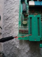
Make sure the EPROM is plugged in the correct way around!Ok that s it i burn it to the 2764 with 0000 offset, now its on the u8 socket on the programmer.what i should do now?
If it is, turn the ELAN on.
What do you observe on the seven-segment displays?
Use you oscilloscope and look at Z80 pin 20 (/IORQ). What do you observe?
Dave
daver2
10k Member
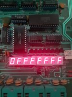
Assuming you have burnt the test EPROM correctly, then the CPU and/or EPROM and/or associated support circuitry appears to not be working correctly.
I would have expected to see activity on the /IORQ signal and for 01234567 (or 76543210) to have appeared on the display with all of the decimal points illuminated.
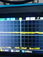
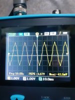
First of all, slow down your timebase. It is too fast at 100 ns/div.
Second, where is the 0V reference on your oscilloscope?
Thirdly, the voltage indicator is 4.92 Volts on the oscilloscope (0.4 V pk-pk), but (at 1 V/div) the display makes no sense at all to me.
Let's make sure the oscilloscope is displaying what it is supposed to be...
Dave
I would have expected to see activity on the /IORQ signal and for 01234567 (or 76543210) to have appeared on the display with all of the decimal points illuminated.
First of all, slow down your timebase. It is too fast at 100 ns/div.
Second, where is the 0V reference on your oscilloscope?
Thirdly, the voltage indicator is 4.92 Volts on the oscilloscope (0.4 V pk-pk), but (at 1 V/div) the display makes no sense at all to me.
Let's make sure the oscilloscope is displaying what it is supposed to be...
Dave
daver2
10k Member
You need to set your oscilloscope PROBE switch (if you have one) to 0V (or short the oscilloscope probe tip to the oscilloscope 0V clip) and then adjust the oscilloscope trace until the horizontal line is one major division UP from the BOTTOM of the screen.
This is where the ground reference is for ALL of our voltage measurements.
Post a photograph of this when you have done it.
Then either select the oscilloscope probe switch to DC coupling, or unclip the probe tip from the ground clip.
Take your measurements.
You should perform this procedure AUTOMATICALLY every time you turn your oscilloscope ON...
The oscilloscope is a voltage against time display. However, in order for the Y-axis to mean anything, we need to know where 0V actually is on the display. Ordinarily, you would set 0V to be in the middle of the oscilloscope screen. But, for TTL signals (that vary from 0V to 5V) you are not using half of the screen. My preference is to set 1V/div and adjust the 0V reference position to be LOWER than mid screen.
On your oscilloscope you have 4 divisions above the middle of the screen and 4 below the middle of the screen. If you set 0V to be mid screen, we can't measure the 5V of a TTL signal (it is off the top of the screen). The oscilloscope will only display up to +4V before it hits the top of the screen.
Does this make sense?
Dave
daver2
10k Member
UNDER NO CIRCUMSTANCE ADJUST THIS.
We will talk about this later...
Dave
We will talk about this later...
Dave
daver2
10k Member
I am not sure what you are saying...
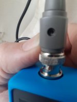
On your oscilloscope probe you should have a probe tip and a probe ground clip. Yes?
If you haven't got the probe ground clip connected to the ground/0V of the device you are measuring, you are relying on the mains safety earth for the ground connection - and that is not sensible.
What I am talking about is where 0V is actually indicated on the oscilloscope screen.
I think we first need to work out whether you know how to use an oscilloscope or not first before measuring anything else.
What have you connected the oscilloscope probe tip to in your photograph in post #156, and where is the oscilloscope probe ground clip connected to?
Dave
daver2
10k Member
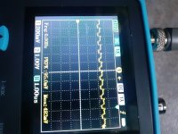
The arrow at the right-hand side is where the 0V reference is. This should be ONE major division UP from the very BOTTOM of the screen.
I also not that you have now set the [1] setting from 1 V/div to 200 mV/div - so this needs to be set back...
Dave
I also not that you have now set the [1] setting from 1 V/div to 200 mV/div - so this needs to be set back...
Dave