• Please review our updated Terms and Rules here

PCI riser cards with multiple slots

mR_Slug

Veteran Member
Joined
Nov 28, 2006
Messages
941
Location
UK
Does anyone know if it's possible to add on additional PCI slots to a PCI bus, with out a PCI-to-PCI bridge?

Ive seen loads of single angled straight-through risers and loads of proprietary versions. The closest thing I've found is this:
https://www.ebay.com/itm/3-Slot-PCI-32-Bit-Passive-Riser-Card-PCI3-B1-2U-000-57270-AR-/181625270319

But it has flyleads. As far as I can see these fly-leads go to the INTA# - INTD# pins.

Are PCI slots not a straight-through bus? I've googled around but even adding "-pcie" nearly everything is about pcie now.
 
No. Unlike ISA slots, each PCI slot has a few pins that are unique to that slot.

At least one difference is each slot has its own designated IRQ line. Which becomes a real headache when trying to sort out IRQ conflicts. Often the only way to change an IRQ with a non-PNP OS is to move PCI cards around.
 
There are slot-specific signals, it's not just wired straight through. Some motherboards do support a riser with two slots on a single motherboard slot, IIRC VIA introduced it on some of their early Mini-ITX motherboards, and a few other Mini-ITX vendors adopted it. I don't know if it was ever standardized. Otherwise, yeah, you require a PCI bridge.
 
The PCI specification is out there; 344 pages but a lot of that is taken up by diagrams. Explains the various slot specific identifiers. Unfortunately, while it shows a sample riser layout, it does not show how the riser needs to be wired together.

If the total number of slots exceeds 3, a PCI-PCI bridge is required.
 
Some complex-function PCI cards even incorporate their own onboard PCI-PCI bridge chips. So you can have more than one bridge in a path. Makes you long for the old days of ISA.
 
I just did a search for the PCI spec and V3 turned up as the first link. Every other time I've searched I've ended up at a page requiring money. So that's good, link:
https://www.xilinx.com/Attachment/PCI_SPEV_V3_0.pdf
Just found 2.1:
http://tesla.desy.de/doocs/hardware/pci/pci21.pdf

I've had a skim read over it. from what I understand the interrupt issue it's not a limitation of PCI per-se, more of a limitation of PCI in a PC. If I've understood correctly.

p39 of v3:
All PCI devices (except host bus bridges) are required to respond as a target to configuration
(read and write) commands. All other commands are optional.

p28: 2.2.6. Interrupt Pins (Optional)
INTA# o/d Interrupt A is used to request an interrupt.
INTB# o/d Interrupt B is used to request an interrupt and only has meaning on a
multi-function device.
[ditto for INTC# and INTD#, that is all cards use INTA# by default]

page 30:
Image1.jpg

So it looks like the interrupt lines are just twisted to make IRQW, INTA# at slot/device 0, connected to INTD# at device 1, INTC# at device 2, INTD# at device 3. But this table indicates this is just so that an interrupt controller can use 4 interrupt lines. It would appear you could connect INTA# straight-thru (and so on), but this would lead to all the cards asserting IRQW all
the time. Leaving IRQX, IRQY and IRQZ to only be used in the rarer case where a PCI device has a second INTB#, third INTC#....function.

Whats more the table indicates that there can be 32 devices with regards to interrupts. My understanding is that this arrangement could go on forever.

I'll have to dig a bit deeper with this, trying to understand "device numbers".

BTW I also found a PCI-to-ISA bridge on an add-in card
http://www.costronic.com.tw/cv72p.htm
I don't know if this would be of any use to those wishing to add FDD's/etc to modern systems. Looks cool though.
 
I think I have a left over 3 slot riser at the office.
It plugs into one slot and then has two other pci card edge connectors on cables to bring the correct signals to the other two slots.


I'll try to remember to drag it out and take a picture tomorrow.

Later,
dabone
 
That "Costonic" ad has been around for a very long time. Notice the "New for 2002.01".

And yet, in spite of interest from various parties, I don't know anyone who has been able to obtain one.

I imagine that DMA gets pretty hairy with an add-on ISA bridge and depends a lot on what your motherboard chipset supports.
 
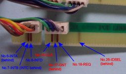
Thanks for that ebay item It has a good shot of the fly-lead. Here's a closeup:
close.jpg

So: CLK GNT REQ and IDSEL (if i've counted correctly) are what I'm going to have to look up tomorrow.

Re: Costonic, the first one is dated 2012, so the website is at least updated somewhat. It is horrendously designed, try the home page!
 
If the total number of slots exceeds 3, a PCI-PCI bridge is required.

Not true. You can have as many PCI slots as you want on the same host as long as the signal integrity constraints are met.

So: CLK GNT REQ and IDSEL (if i've counted correctly) are what I'm going to have to look up tomorrow.

Most riser cards have a cascaded local arbiter to handle REQ/GNT. Each card slot can request control of the bus through REQ and must wait until granted (GNT). There are limits on how long the card in the slot can hold the bus. CLK is probably there so it can be rebuffered for fan-out concerns. IRQs are meant to be shared across multiple cards. IDSEL is usually wired to unique address lines per slot so that the configuration space of each slot is separated in the address space. Risers have to handle this carefully as to not conflict with the on-board IDSEL distributions.

-Alan
 
My P4 IBM has PCI expansion installed that adds like 3 slots but it seems to be proprietary hardware.
 
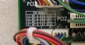
Thanks dabone for the image, confirms my drawing perfectly. I've tested an actual 440BX based motherboard and there is no continuity between each PCI slots on CLK, GNT, REQ and IDSEL.

As eeguru points out, CLK does not have to be point-to-point:

The 2.1 spec states that CLK can be wired as a bus or point to point:
"CLK to Signal Valid Delay - bused signals Min:2 Max:11 ns
CLK to Signal Valid Delay - point to point Min:2 Max:12 ns"
(p150)

also found:
"This includes individual REQ# and GNT# signals for each connector." (page 23)

"REQ# and GNT# are point-to-point signals, and have different output valid delay and input setup times than do bused signals. GNT# has a setup of 10[ns]; REQ# has a setup of 12[ns]. All other signals are bused."
(page 150)

However REQ# and GNT# are for busmaster only. So it would appear that a straight-though 1-to-2 or 1-to-3 riser would work with PCI cards provided they aren't busmasters.

I'm having trouble understanding the IDSEL pin. The last quote would indicate that it can be bussed but then the following quote indicates it is not (as confirmed with the board tested).

"However, accesses in the Configuration Address Space require device selection decoding to be done externally, and to be signaled to the PCI device via the IDSEL pin, which functions as a classical "chip select" signal." (page 100)

Then the following quotes indicate that it is not a simple "enable device" pin, as there is a configuration protocol of devices responding over the address bus.

"Implementation Note: System Generation of IDSEL
How a system generates IDSELs is system specific; however, if no other mapping is required, the following example may be used. The IDSEL signal associated with Device Number 0 is connected to AD16, IDSEL of Device Number 1 is connected to AD17,
and so forth until IDSEL of Device Number 16 is connected to AD31. For Device Numbers 17-31, the host bridge should execute the transaction but not assert any of the AD[31::16] lines but allow the access to be terminated with Master-Abort."
(page 101)

"Device Number is an encoded value used to select one of 32 devices on a given bus. (There are only 21 devices that can be selected by tying the IDSEL to an AD (AD[31::11]) line.)" (page 103)


So If I'm understanding this correctly, say a motherboard has 4 slots. IDSEL at slot 0 is connected to AD16, slot 1 to AD17, slot 2 to AD18, slot 3 to AD19.

If there is a 3 slot riser in slot 3, one slot on the riser would have IDSEL connected to AD19, then the additional 2 slots would need to have the IDSEL connected to AD20 and AD21. And then to the motherboard it would appear that there are now two additional (non-busmastering) slots. Have I understood this?
 
REQ# and GNT# are always per-slot. You can't tie them together at all. Even the most basic of risers have a small chip with enough pins for power and REQ/GNT to each slave slot and the up-stream slot - usually a fixed priority arbiter. In order to take control of the bus, you have to assert REQ# and wait for GNT#. Then each card has to monitor for GNT# de-assertion and truncate the bus cycle if necessary.

I'm having trouble understanding the IDSEL pin. ...If I'm understanding this correctly, say a motherboard has 4 slots. IDSEL at slot 0 is connected to AD16, slot 1 to AD17, slot 2 to AD18, slot 3 to AD19.
IDSEL is for reading the configuration address space - a purely PIO operation. The exact configuration of how it is wired is up to the implemented of the master bridge device. Some controllers have a single 64K config window in main address space along side a slot selection register to define which IDSEL goes active when the config space is read. That's typical for a master bridge in an embedded SoC. Most PC master bridges, however, just run different address lines to each IDSEL and allocate a many-megabyte config access window. Thus slot 0 config is at offset 0, slot 1 is at offset +64KB, slot 2 at +128KB, slot 3 at +256KB, slot 4 at +512KB etc... and usually aliases beyond that as the rest of the address lines remain unqualified.

If there is a 3 slot riser in slot 3, one slot on the riser would have IDSEL connected to AD19, then the additional 2 slots would need to have the IDSEL connected to AD20 and AD21. And then to the motherboard it would appear that there are now two additional (non-busmastering) slots. Have I understood this?

Every slot must always be able to busmaster. That's where the on-board arbiter is required to multiplex REQ#/GNT# - and usually a clock buffer to handle the increased fan-out.

Just to add, I did a fixed priority arbiter design a while back from a 22v10 that would work perfectly fine on a PCI riser without any changes. Can read about it here.
 
Back
Top