daver2
10k Member
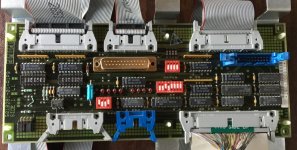
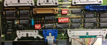
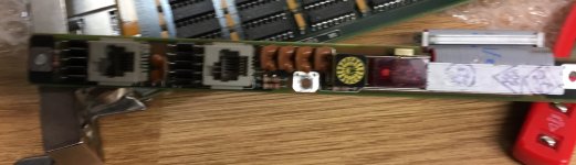
Sorry Steve, you are still not photographing the correct part of the front panel. It is the top (narrow width) of the panel, not the long side.
Yes. If the rotary switch is used, the links should be removed. Likewise, if the links are used, the rotary switch (if it exists) should be set to a specific setting. If we have the links installed and the rotary switch set to a valid setting - they will result in the CPU setting the baudrate to the wire-OR of the links and the switch setting. Not the desired outcome...
I’ll have a look for the manual I found with a poor-quality photograph.
Dave


")