So,
@ZachyCatGames hooked up our Saleae Logic Pro 16 and scoped some of the signals around LC00 and LC01 while running Zach's code. The things we were looking at are on Page 145 of the MM Vol. III:

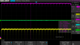
What we saw didn't make a lot of sense -- signals at S2 and N1 were extremely rare (which is different than our oscilloscope screenshot from the other day).
So, we decided to scope just four things: LTT TP0 L (M113 C16 P1), LTT TP3 L (M113 C16 R2), LTS LC 02 1 (H) (M113 C16 S1), and LTS LC 02 (0) H (M113 C16 S2) -- the NOR clock in C16.
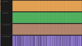
When we did that, TP0 (P1), TP3 (R2), and 02 (1) H (S1) all seemed "normal" (or at least consistent), but 02 (0) H (S2, which feeds D19 N1), was very inconsistent. Since all the signals are on the same card (no wire wrap involved), I swapped the M113 back from before (recall that I swapped two the other day), and i also tried to clean the clip chip slot with some deoxit and paper towel on the flip chip for C16. When we next captured, the signal on S2 seemed improved, but is still quite flaky:

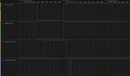
If you zoom in, it looks even weirder:

P1, R2, and S1 all have signals of roughly the same length (~60ns), but the S2 changes -- when they happen to occur -- are tiny, in the single digit ns. I don't know if those are instrumentation glitches, or what. Zach added a speaker click to when the Tape Word Flip Flop is set, and we can hear that it is getting set, but very inconsistently.
So, what would you suggest as a next step? Should I try to give the FC slot a deep clean? How should I go about doing that? Am I misunderstanding what I'm seeing here, or what the LC 02 (0) H signal should look like? I'll attach the capture file, which can be
viewed in Saleae's Logic 2 program.
Any advice will be greatly appreciated!


