• Please review our updated Terms and Rules here

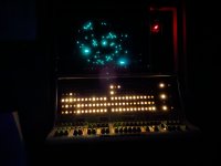
PDP-12 #435 at the University of Minnesota Duluth

I could probably part with one also, and domestic shipping is bound to be cheaper.
Hello Vince, this is of course the case. Thanks a lot, will take the next occasion in Europe!

We discussed the spar part problematic a bit and would like to ask, what is a basis of spare parts for the PDP12?
The list gets easily long, but what is really necessary?
 
Seems like caps look good...?
 

Attachments

  • PXL_20240930_203343786.jpg
    PXL_20240930_203343786.jpg
    2 MB · Views: 6
  • PXL_20240930_203328575.jpg
    PXL_20240930_203328575.jpg
    2.3 MB · Views: 6
Last edited:
.. what is a basis of spare parts for the PDP12?
The list gets easily long, but what is really necessary?
Ideally, one (known good) of each module type. When I had to go troubleshoot PDP-12's I'd just grab the field service module spares kit and hope it hadn't been depleted too badly from whoever last used it. If the spares kit wasn't available I was often able to diagnose the suspect module by swapping identical modules from another part of the circuit and see if the symptom changed as expected.
 
Pins 9 and 10 are the unbuffered oscillator, so if that is oscillating but D and E aren't, then the 7400 is likely at fault. (I think pin 12 should be ramping up and down.)
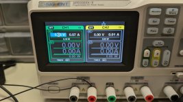
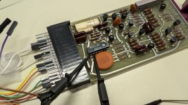
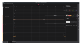
Hi @vrs42 -- @ZachyCatGames and I hooked up our M401 to the power supply and the Saleae to pins 9 and 8 of the 7400 and also to D2 and E2, the high and low outputs of the FC. The logic analyzer was in analog mode @ 50MS/s. See attached images.

Pin 9 (9 and 10 appear to be tied outputs from the oscillator) is high at about +2.66V, and pin 8 is low (since both pins 9 and 10 are NANDed). The rise and fall is when power is turned on and off at the supply. There does not appear to be any oscillation, but it seems meaningful that there's at least a high signal on pins 9 and 10. (It's not dead.)

Any suggestions on what to check next? Thanks!
 

Attachments

  • power-PXL_20241001_162630286.jpg
    power-PXL_20241001_162630286.jpg
    350.4 KB · Views: 11
  • m401-probes-PXL_20241001_162624159.jpg
    m401-probes-PXL_20241001_162624159.jpg
    648.4 KB · Views: 11
  • image.png
    image.png
    111.8 KB · Views: 11
Last edited:
Hi all, @antiquekid3 had the great suggestion to see if there is someone here in UMD's EE department who could help us learn how to safely debug the flip chip. We know one or more of the components has gone bad, but we're not sure how to safely test or reason about the oscillator circuit. A little bit of hands-on tutorial should go a long way in helping with this and future issues. We're always willing to try anything anyone might suggest, but barring that, I'll wait until after we get a little local advice. Thanks again for all the help and encouragement!
 
Any suggestions on what to check next? Thanks!
My problem is that there are a bewildering array of discrete components. Nearly 3 times as many as I expected.

I assume that the 47 pF capacitor, the .01uF capacitor at pin S, the 10K potentiometer, and the 150 ohm resistor form the main RC network, whose charging rate determines the frequency.

Basically, the transistors should switch off and on in such a way that this RC network charges up to a threshold, then things switch over until it discharges to another threshold and switches back. But the details of how that is done are still lost on me, so I'm not much help.
 
Astable circuits like this tend to be the bread&butter of radio folks, so it does sound like someone in the EE department might be quicker on the jump at pinpointing the root cause.
 
Any suggestions on what to check next?
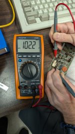
Easy first check is use meter on diode test and check forward drop of diodes and transistor b-e and b-c junctions. Should be around 0.6 to 0.7 volts. Sometimes components in circuit can cause reading that look bad. Always nice to have another board to check against to see if it has same reading.
 
Easy first check is use meter on diode test and check forward drop of diodes and transistor b-e and b-c junctions. Should be around 0.6 to 0.7 volts. Sometimes components in circuit can cause reading that look bad. Always nice to have another board to check against to see if it has same reading.
I just found a DEC transistor that had a E-C short, and the B-E and B-C voltage drops measured OK. Spend another 10 seconds and make sure that the E-C is isolated both ways.
 
@pahp have you turned the knob on the variable resistor? The contact inside could be oxidized so I would turn it several turns in one direction, then back the other way e.g.: 5R, 10L, 5R so back to where it was. Also, look for cold solder joints and possible shorts between pins that are close to each other. Nearly invisible wires or solder splashes can cause shorts. Brush away anything fuzzy. Clean flux residue with proper solvent. From your photo PXL_20240927_133350286~2.jpg, I'd check pin 3 (if I'm counting correctly) of the 7400. It might need to be re-flowed. Solder joints should be bright and shiny. If dull or fuzzy, then re-flow and clean.
 
Last edited:
Hi @MauryP , @m_thompson , @djg , @vrs42 and all -- we will try all these things -- thanks! Also, now that we have a schematic for the M401H (thanks, @vrs42 !) we can also try @DougIngraham 's suggestion of looking at it in ltspice.

I also took @antiquekid3 's suggestion and made a connection with someone in EE who should be able to teach us how to best use our gear (and maybe help debug the oscillator). He won't be available for about a week and a half, though.

Anyway, hopefully we will have more to talk about, soon! Thanks again.
 
Back
Top