Hugo Holden
Veteran Member
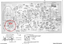
Unfortunately i can't found Q14 in this video board
http://www.zimmers.net/anonftp/pub/cbm/schematics/computers/pet/2001/video-layout.gif
See attached image.
Unfortunately i can't found Q14 in this video board
http://www.zimmers.net/anonftp/pub/cbm/schematics/computers/pet/2001/video-layout.gif
A 16% increase in voltage is about a 36% increase in dissipated power.
Dwight
See attached image.

Good morning guys!
I have now removed Vr1 and i measure 25V on the board but i can't found 12v or 14v now....
Where should i read 12v?
Thanks at all for precious help!
Yes, I got R3 backwards. The end of R3, closest to the regulator is ground!!
Sorry about the confusion. I don't have a real board to look at.
Dwight
You are missing the screw to screw the regulator down. That is important to get good thermal contact of the regulator to the heat sink. The connection to R3 looks right. After you replace the screw we can power things up and run some experiments with Q11, Q12 and Q13.
Check that the wire at the regulator isn't shorting to the other lead and tidy up your R3 lead by removing the tail of wire.
Dwight
I'm looking at the picture. What value does the regulator say on it. Is it 7814 or 7812?
Dwight
We have clearly all fallen into a parallel universe where the Laws of Physics are different!
As Dwight has said, something is clearly wrong somewhere and we need to track it down. The 7812 is rated up to +30V at the input, so what you are reading is high, but within the limits for the 7812 - albeit with increased power dissipation.
I liked the idea of a high resistance joint on the GND side of the 7812; but, assuming the wire has been connected correctly, that should now rule that out.
Just thinking if measuring the input to GND voltage, the output to GND voltage and the differential across the regulator from input to output will tell us anything? The voltages measured should (at least) be consistent...
Dave