Upcoming Events:
- VCF South West - June 14 - 16, Davidson-Gundy Alumni Center at University of Texas at Dallas
- VCF West - Aug 2 - 3, Computer History Museum, Mountain View, CA
- VCF Midwest - Sept 7 - 8 2024, Schaumburg, IL
- VCF SoCal - Mid February 2025, Location TBD, Southern CA
- VCF East - April 2025, Infoage Museum, Wall NJ
-
Please review our updated Terms and Rules here
You are using an out of date browser. It may not display this or other websites correctly.
You should upgrade or use an alternative browser.
You should upgrade or use an alternative browser.
Problems booting PDP-11 through tu58 emulator
- Thread starter RetroNewbie
- Start date
thunter0512
Veteran Member
I don't like the desoldering tools where the vacuum pump is integrated in the handset (like the Hakko FR-301). These vibrate and cause damage to tracks.Another thumbs-up for the Hakko FR-301. By far the best desoldering tool I've ever used.
You are much better off with with a desoldering station where the vacuum pump is in a separate box (like the Hakko FM-204).
Of course there are many cheaper alternatives to Hakko.
RetroNewbie
Experienced Member
That sounds like a lot of work.I understand, but be aware that you are probably more likely to damage traces on the board then you are getting a chip out in one piece that is reusable.
The only time I had to do that I very carefully cut the pins off away from the body, leaving about 1-2mm of pin protruding.
I then soldered the 16p chip to DIP form factor component carrier so I could test it offline in a standard DIP compatible breadboard.
One of these things...
View attachment 1269765
Maybe I'll just wait for replacements then
daver2
10k Member
The key parameters for a replacement are:
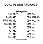
1. The same pinout as the original [note especially where VCC (+5V) and VSS (0V/GND) is located]:

2. 128 cycle / 2 ms refresh (not 256 cycle).
3. /RAS only refresh.
4. 150 ns (or better = faster) access time.
5. 260 ns (or better = faster) cycle time.
6. Power dissipation not greater than 300 mW (when active).
If unsure, post a link to what you are planning to purchase and I am quite happy to check.
Dave
1. The same pinout as the original [note especially where VCC (+5V) and VSS (0V/GND) is located]:

2. 128 cycle / 2 ms refresh (not 256 cycle).
3. /RAS only refresh.
4. 150 ns (or better = faster) access time.
5. 260 ns (or better = faster) cycle time.
6. Power dissipation not greater than 300 mW (when active).
If unsure, post a link to what you are planning to purchase and I am quite happy to check.
Dave
shirsch
Veteran Member
My experience has been the exact opposite, FWIW. The hose on those 2-part systems acts like an inductor to "blunt" the initial pulse of vacuum. The one-piece unit I have (FR-301) is far more reliable for clearing holes in multi-layer boards.I don't like the desoldering tools where the vacuum pump is integrated in the handset (like the Hakko FR-301). These vibrate and cause damage to tracks.
You are much better off with with a desoldering station where the vacuum pump is in a separate box (like the Hakko FM-204).
Of course there are many cheaper alternatives to Hakko.
Al Kossow
Documentation Wizard
My experience has been the exact opposite, FWIW. The hose on those 2-part systems acts like an inductor to "blunt" the initial pulse of vacuum. The one-piece unit I have (FR-301) is far more reliable for clearing holes in multi-layer boards.
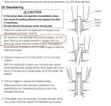
He's using the tool incorrectly.
The nozzle shouldn't be touching the traces at all.
Attachments
AK6DN
Veteran Member
It was, but I am not suggesting that is the norm. This was a special case where I needed/wanted to test the removed chip functionality on a separate test fixture.That sounds like a lot of work.
Maybe I'll just wait for replacements then
The normal means of just cutting the pins off flush with the body (making for maximum length pins left in the PCB for easier removal) precludes testing the chip after removal.
The other scenario is you are just trying to salvage some chips from an old dead board for reuse (ie, making 'pulls'). In that case a professional grade desolder tools is warranted.
Last edited:
RetroNewbie
Experienced Member
Thank you!The key parameters for a replacement are:
1. The same pinout as the original [note especially where VCC (+5V) and VSS (0V/GND) is located]:
View attachment 1269770
2. 128 cycle / 2 ms refresh (not 256 cycle).
3. /RAS only refresh.
4. 150 ns (or better = faster) access time.
5. 260 ns (or better = faster) cycle time.
6. Power dissipation not greater than 300 mW (when active).
If unsure, post a link to what you are planning to purchase and I am quite happy to check.
Dave
I'm tempted to get them on aliexpress instead of ebay since in my experience the shipping time is almost the same (if not more) from ebay sellers from France or neighbouring countries than with Aliexpress.
On aliexpress you can find the ICs with the exact same marking "MK4564N-15".
But I know that there have been problems with fake ICs that are slightly different versions (usually slower) than what advertised so I'm not sure of that.
RetroNewbie
Experienced Member
I see, in the end I removed the bad IC destructively and did so succesfully, thank you for the suggestion!It was, but I am not suggesting that is the norm. This was a special case where I needed/wanted to test the removed chip functionality on a separate test fixture.
The normal means of just cutting the pins off flush with the body (making for maximum length pins left in the PCB for easier removal) precludes testing the chip after removal.
The other scenario is you are just trying to salvage some chips from an old dead board for reuse (ie, making 'pulls'). In that case a professional grade desolder tools is warranted.
daver2
10k Member
I would be dubious of Aliexpress to be honest.
However, if you install an IC socket, you can always replace it easily.
The problem is, if you install a counterfeit part, you don't know whether it is the part that is faulty or the memory board is faulty for another reason...
I would be inclined to buy a part from a trusted source.
Dave
However, if you install an IC socket, you can always replace it easily.
The problem is, if you install a counterfeit part, you don't know whether it is the part that is faulty or the memory board is faulty for another reason...
I would be inclined to buy a part from a trusted source.
Dave
RetroNewbie
Experienced Member
You're right, definitely not best for debugging. I guess I'll go on with ebay then. Not sure how much more trusted that can be though.I would be dubious of Aliexpress to be honest.
However, if you install an IC socket, you can always replace it easily.
The problem is, if you install a counterfeit part, you don't know whether it is the part that is faulty or the memory board is faulty for another reason...
I would be inclined to buy a part from a trusted source.
Dave
daver2
10k Member
Aren't there any surplus part suppliers in Itlay?
Dave
Dave
RetroNewbie
Experienced Member
Not that I know of. My knowledge in the field is very limited though.Aren't there any surplus part suppliers in Itlay?
Dave
An ebay seller should do, there are parts with the exact same marking so they should do fine.
RetroNewbie
Experienced Member
In the end I bought two of the exact same ICs from ebay. I'll make a new post when I receive and try them.
leegleason
Experienced Member
- Joined
- Jan 20, 2014
- Messages
- 150
When I'm salvaging chips from an old dead board, I grab the board with vise grips, heat the backside with a propane torch until the solder melts, and whack the board on the ground so the chips fall out. I've salvaged hundreds and hundreds of ICs this way. Outdoors, naturally - the smoke from the hot boards smells awful and is no doubt toxi and carcinogenic.The other scenario is you are just trying to salvage some chips from an old dead board for reuse (ie, making 'pulls'). In that case a professional grade desolder tools is warranted.
I've used that method also. They 'look' OK, but I didn't have a good way of doing any functional tests on the salvaged chips. Have you been able to check if most of them are still usable? I found it slow going due to most of the IC's having power and ground pins crimped which kept them from falling out. Appropriately adjusted locking pliers solved that problem.heat the backside with a propane torch until the solder melts, and whack the board on the ground so the chips fall out.
leegleason
Experienced Member
- Joined
- Jan 20, 2014
- Messages
- 150
I haven't done any systematic testing, but I've been using the salvaged chips for a very long time now on lots of projects and haven't had any problems with them.I've used that method also. They 'look' OK, but I didn't have a good way of doing any functional tests on the salvaged chips. Have you been able to check if most of them are still usable? I found it slow going due to most of the IC's having power and ground pins crimped which kept them from falling out. Appropriately adjusted locking pliers solved that problem.
RetroNewbie
Experienced Member
Thank you for all the help so far! I've received the IC and replaced them. The lower memory bank now passes the memory test without any problem.
So I wanted to try and boot an OS from the tu58 following these:
- https://www.computercollection.net/wp-content/uploads/2019/11/BuildRT11TU58Image-20191004.txt
- https://forum.vcfed.org/index.php?threads/wanted-rt-11-os-as-a-tu-58-image.39724/
But I failed since I can't get RT-11 to interface with the tu58.
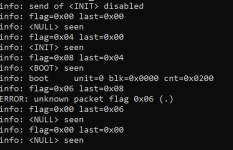
So I tried booting some pre-made images to ensure that everything is working. I tried using 11xx_1.dsk from here. But that didn't work, I'm not sure if I'm doing something wrong, if the image that I chose is not bootable or what. This is the output:

I got this with the following command "tu58em.exe -p 10 -d -v -s 9600 -r xx.dsk -T" and using the bootstrap code found here
Sometimes instead of getting an error the program just halts at the boot command
So I wanted to try and boot an OS from the tu58 following these:
- https://www.computercollection.net/wp-content/uploads/2019/11/BuildRT11TU58Image-20191004.txt
- https://forum.vcfed.org/index.php?threads/wanted-rt-11-os-as-a-tu-58-image.39724/
But I failed since I can't get RT-11 to interface with the tu58.
So I tried booting some pre-made images to ensure that everything is working. I tried using 11xx_1.dsk from here. But that didn't work, I'm not sure if I'm doing something wrong, if the image that I chose is not bootable or what. This is the output:

I got this with the following command "tu58em.exe -p 10 -d -v -s 9600 -r xx.dsk -T" and using the bootstrap code found here
Sometimes instead of getting an error the program just halts at the boot command
AK6DN
Veteran Member
Classic display when there is a serial port issue.
Mismatch in configured baud rate or stop bits. Unreliable serial interface operation.
The 11xx_1.dsk should boot on your system. All the TU58 images in that location are bootable XXDP images.
What TU58 bootstrap are you using? You don't indicate. Found the link to the bootstrap (thanks Dave, next post!). That code should work fine.
So my guess is as I stated earlier a serial port issue.
Mismatch in configured baud rate or stop bits. Unreliable serial interface operation.
The 11xx_1.dsk should boot on your system. All the TU58 images in that location are bootable XXDP images.
So my guess is as I stated earlier a serial port issue.
Last edited:

