• Please review our updated Terms and Rules here

RAMdisk under CP/M 2.2

Why not? 14 hours is a good overnight burn-in.
Well, you are correct. the first go around using a BASIC program that runs that long would be good. But after that, I need something in assembly that takes much less time. BASIC is easy for that first run of burn-in and confidence testing.
 
Congratulations on another working project ! :)

Is the test running under MBASIC, or is it in assembly? 14 hours seems a but much for 512K of Ramdisk... 14 minutes I could understand.

Did you manage to integrate it with the shell, or are you using commands from the command line to access it?

I'd love to see the code you generated to test it - :)

David
This first run is BASIC, and I am really only looking for a confidence type test for any future use. You are correct, I could go really hardcore, but a average test should fit the bill. And yes, I will certainly post the code.
 
You might want to think about what you want to test: the RAM, the mapping hardware, etc. Also, writing the same byte to all of memory may miss some types of errors. You might think about a rolling pattern, even something as simple as an incrementing BCD byte (0x00 ... 0x99) - which is pretty easy to do with the DAA instruction. You keep a "seed" byte that is the first value, and then you can vary the pattern on each pass. This pattern is pretty much guaranteed not to repeat when used on any power-of-two sized storage (i.e. will catch errors that repeat on address-line patterns). You also probably want to write a pattern to all of RAM first (different pattern to each sector, or a rolling pattern that doesn't repeat on address lines), then check it, as that ensures the mapping is working correctly (otherwise, you can't tell if you're re-writing the same sector over and over).
I'm just looking to do the standard tests. I remember in the days of 1Kx1 2102 RAM chips we did all sorts of bit tests, but with using 32Kx8 chips, if one cell is bad, it is easy to figure out which of the six chips is at fault and swap it out.
 
Well, if I could only get a program to provide more hours in the day.... Short of that, I am making progress on at least the memory chip test program for this project. I can now cycle through all of the addresses (tracks, sector, & bytes of the RAMdisk) and get the display part working. Next part will be the read back of the location and then error testing. Here is what I have so far. Then I'll clean out the unused junk from the code.
 

Attachments

  • MDTEST.pdf
    35.5 KB · Views: 6
Well, if I could only get a program to provide more hours in the day.... Short of that, I am making progress on at least the memory chip test program for this project. I can now cycle through all of the addresses (tracks, sector, & bytes of the RAMdisk) and get the display part working. Next part will be the read back of the location and then error testing. Here is what I have so far. Then I'll clean out the unused junk from the code.
Did you find any errors? Modern computers gave up RAM tests somewhere around 1985 IIRC, so I often wonder how much the RAM tests are needed and what value they give outside of repair activities.

Mind you, I have a microcontroller that can't complete the same maths routine without occasionally giving a wrong result, and it's a linear calculation involving only a few ALU operations, so maybe a ram check is still useful at times.

I noticed you're using a table to convert to hex. Just curious about the reasoning for this over a calculation-based conversion?

eg; https://forum.vcfed.org/index.php?t...i-hex-conversion-rehash-of-an-old-idea.26636/

Regards
David
 
I am actually using the RAM test as more of a way to confirm the hardware design and no wiring errors. Given the circuit relies on six 32Kx8 SRAM chips, it sure isn't like the old 2102's when it comes to troubleshooting. As for the hex conversion, i just borrowed the code segment from something I had readily available. And kinda like use what you know.....
 
Did you find any errors? Modern computers gave up RAM tests somewhere around 1985 IIRC, so I often wonder how much the RAM tests are needed and what value they give outside of repair activities.


Regards
David
Out of interest on this question, I was initially having so many problems with the RAM in my SOL-20 initially, I put a MEMTEST program in ROM and I would run it every time prior to using the computer. If a sector of memory drops out, the computer just freezes sometimes and it is hard to know what caused it, if it was the program running or many other things.

This was mainly because, before I fixed the many defects on the PT 16kRA DRAM cards, they were very intermittent. Everything from poor DIP switches making the cards intermittently non-responsive over a specific address range, or poor IC socket & pin connections, faulty delay lines etc. The Seattle Computer standard 16k static RAM card by comparison never gave trouble. After a full restoration of three PT 16kRa cards I got them to be as reliable as the SRAM card and started to skip the memory testing, but without the MEMTEST program at hand initially, it would have been much more difficult. Plus, it is useful to activate the card, which helps with scope testing them. It also pays to make a memory fill program at hand, so as to be able to examine and diagnose specific defects in different bits. I put that into ROM as well.

Maybe the memory test utilities became a lot less useful when the RAM itself became much more reliable.
 
I also build RAM test into my monitor. I do have big DRAM in one of my Z80 SBC, and even if the RAM itself is reliable, It is useful to check out the address, data, communication with console after a few weeks of inaction.
Bill
 
I have been beating my head over trying to get a memory test to work for this MemoryDisk board and I 'think' I might being getting close, but this is still stumping me. When I run the test, all I seem to get are errors that show expected and actual both equal '00'. so obviously I have a code problem somewhere. But i am really getting stumped over this. Maybe I should regroup and just write a test program that tests various patterns on a single address and see what happens. I am sure open to thoughts at this point.
 

Attachments

  • MemoryDiskv5.pdf
    86.1 KB · Views: 2
  • MDTEST.pdf
    77.2 KB · Views: 3
One thing to note about Z80 (all 8080-family) code is that instructions like "ld a,b" do not alter the flags. In general, "ld" instructions do not change the flags, mostly only ALU and INC/DEC. You'll need to check the instruction documentation to be sure it is valid to check the flags, and which ones, after a given instruction.

It also appears that you may be trashing registers in some of your routines, but the caller expects the value(s) to be preserved. I think that is happening in your "error_found" path (likely causing wrong values to be printed), probably other places as well.
 
Doug, I was actually thinking along similar lines. In fact, I wound up starting from scratch with a very simple test of a single byte, of a single sector, of a single track, with all 12 patterns I want to test. And that worked and displayed exactly what I wanted. This evening I added additional code to test all 256 bytes of each sector, and all 256 sectors of each of the three tracks. And that code works as well. Well, almost. I am getting weird data read back whenever I write the FF pattern. All the other eleven patterns are rock solid. But the FF, while displaying FF the majority of the time, will sometimes comeback with something completely different. Tomorrow I will run the test on the entire array and see if it may be related to the hardware. Since the array has two 32Kx8 chips that have a different address bit signal pattern that the other four, maybe that maybe an issue.

There was a previous post I made somewhere here discussing that. Both devices have the address bits on the same 15 pins, but one device has A14 on pin 1, while the other has A5 on pin 1. I guess I will find out tomorrow. Then I have to figure out if the issue is that the data is written wrong. of if it is read back wrong. Just odd that it is just that one pattern of the 12. Oh well.
 
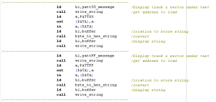
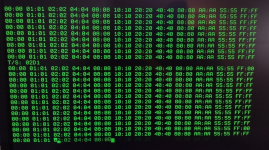
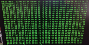
Well, it gets weirder and weirder. I rewrote the test code and noticed that eleven of the twelve patters get written and read without error over the entire array. But when writing the 'FF' pattern I would get random garbage. Since I did not run the test on the entire array yesterday, I decided to do that today. And the same issue was occurring. That says there isn't a memory chip problem. But I got to thinking that maybe there was a problem of some sort with the 74LS244 that is part of the data read circuitry to put the data on the buss. Given that the last pattern written for each memory cell is 'FF', I decided to write a real quick MBASIC program to just read each memory cell and display the contents. And, it turns out that every cell contains an 'FF'. So that should rule out a hardware problem. Then is it software related. Given that I use the same routine for writing and reading each data pattern, it is hard to believe it is software. How often have you heard "it's not a software problem"? I wonder if there might be a timing or placement issue? I may swap the '55' and 'FF' sequence and try tomorrow. If the issue shows up when writing the '55' pattern, then that may be where to look next. I attached the code if anyone is interested (sorry for the poor format, eDevStudio isn't great in how it formats it's .asm output file).

1681840385056.png1681840557899.png1681840594606.png
 

Attachments

  • MDSGLTST.pdf
    72 KB · Views: 4
This may seem unlikely, but check that you have SOLID power and ground to all your chips - especially the data bus driver(s). I've seen chips act strange when, for example, ground is not connected - depending on the number of "0"s on inputs, the chip might function correctly. That would certainly explain why 0xFF is not working.
 
Doug, I was sitting and thinking, and thought, what if it is a bit pattern thing. So I made some changes using the these patterns (F0, 0F, A0, 0A, 50, 05, A5, 5A, 00, FF, AA, 55) and in that order. Oddly enough, the problem was still with FF. My next test is going to be a F4, F5, F6, F7, F8, F9, FA, FB, FC, FD, FE, FF pattern. And then that in reverse. And then swapping the digits to be 4F, 5F, 6F, 7F, 8F, 9F, AF, BF, CF, DF, EF, FF. and then swap those digits. I suspect that the problem will always show with the FF pattern no matter where it is. So, who knows. And since I also have an extender card, I may put the board on an extender to see if that changes anything. Debugging is so much fun! LOL
 
Well, the F4, F5, F6, F7, F8, F9, FA, FB, FC, FD, FE, FF pattern seems to be even worse. I took another look at the circuitry and I'm wondering if I should have some pullup resistors on the data lines on the internal data buss. I was relying on the memory chips to drive the signals high or low accordingly, but maybe pullups should be used. I'm going to look into adding those and see if that changes anything.
 

Attachments

  • MemoryDiskv5.pdf
    86.1 KB · Views: 5
This is time to ask how the circuit is implemented? Pictures of the board (backside and front side) are helpful. High speed parts are more problematic from system noise point of view. Ground needs to be solid. if your supply voltage is adjustable, does the problems get worse at higher or lower voltage? Does that problems change when you probe different part of circuits? Pattern sensitive errors can be caused by ground bounce, reflection, and contention.
Bill
 
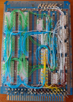
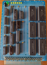
Here are the front and back pictures of the board. I think I will add some more decoupling caps and a bigger filter cap and a pullup resistor network sometime today to see if that helps. I like to use different color wirewrap wire for the different signal types. The green LED is for power indication, and the six yellow LEDs are for the chip selects for each of the memory chips. It is STD buss based.

1681908087640.png1681908118816.png
 
Well, adding a couple more decoupling caps an a small filter cap and pullup resistors (6.8K) to the internal data buss had no effect at all. I even swapped out the memory chips with no effect as well. I wonder if there could be a loading issue with the internal data buss; since there are 10 devices on that buss. Or possible a cross-talk issue. Head scratching time I guess.
 
I’m not a fan of the “tuning fork” power and ground distribution. I normally solder short jumper wires from tip to tip of the “fork” to form a grid, especially the ground.

AS6C62256 was the culprit in this very long discussion about memory problem. I duplicated the circuit under discussion and used AS6c62256 as well but did not observe the memory problem, yet several forum members did have similar memory problems. So AS6C62256 may be more sensitive.


Bill
 
Back
Top