• Please review our updated Terms and Rules here

SBC6120 "Mini" Front Panel

Hi Aug,

my SBC6120-RBC runs fine too when operated via the serial port. The problem is that the front panel stops updating when the count wraps from 7777 to 0. The SBC6120-RBC continues to count and seems to do a full count cycle from 0000 to 7777 when then the front panel updates resume.

To replicate the problem, power on the system, but don't type anything on the serial console. Then enter the following count program starting from address 0000 and extended address 0000 via the front panel switches using the DEP toggle. After setting the address back to 0000 verify it via the EXAM toggle. Finally set the address back to 0000 again and then select the AC display via the rotary switch and toggle CLEAR and then CONT to start the program. Observe how the count reaches 7777 and then there is a long pause after which the count resumes at 0000.

Here is the count program (the text after the ";" is the PDP-8 instruction mnemonic):

0000: 7001 ; IAC
0001: 2101 ; ISZ 0101
0002: 5001 ; JMP 0001
0003: 5000 ; JMP 0000

If while the count is paused, you type a single character for example SPACE, the front display resumes and won't ever stop again.

If you enter and start the same program via the serial console, the count increments from 0000 to 7777 and then immediately resumes incrementing from 0000 as you would expect.

Could you please explain why you think that the PAL manufacturer (Lattice vs Atmel) may be the cause of the problem?

I am using the Atmel parts: ATF16V8BQL-15PU and ATF22V10CQZ-20PU

I used the JED files in directory "sbc6120-rbc-edition-archive-10may2018\PLD" from the SBC6120-RBC site to program the PLDs. After programming the PLDs verified OK.

I would appreciate any insights you have.

I also have an original FP6120 front panel from Bob Armstrong with an SBC6120-RBC processor board and it has the same pausing problem.
I believe the original SBC6120 processor board from Bob Armstrong works fine with either Chris's or original front panel boards.

Thanks
Tom
The 22 Lattice pals are slower. 25 vs 20. Somewhat a stab in the dark. Also the SBC uses different memory. It will be a week or so before all parts arrive. Some are still stumbling thru the Aliexpress shipping maze.

Aug
AG5AT
 
I have swapped the 3 PALs between the working original SBC6120 and the pausing SBC6120-RBC. The hang problem stays with the SBC6120-RBC despite the PALs from the working unit. The original SBC6120 does not exhibit the front-panel pause.
The pause problem is not caused by the PALs.
 
I swapped the HD6120 CPUs between working original SBC6120 and the pausing SBC61120-RBC. The problem stayed with the SBC6120-RBC.

Next I swapped the UARTs between the two units. It turns out that the problem follows the UART.

The UART causing the pauses is this one:

Bad_UART.jpg

I have 3 of these and tried all of them. They work fine as a UART, but they all exhibit this pausing problem when used with either Spare Time Gizmos FP6120 or Hideehoo's front panel.

I subsequently tried an Intersil and also a Harris version of this chip and they works perfectly as a UART, but also these dont cause the pause of the front panel updating.
 
Even if that's some shady counterfeit part trying to phone home (which makes no sense), I don't get how that could prevent the front panel from updating.
 
I'm hardly an expert on counterfeits but something about the labeling on that chip looks off. Characters do not exactly line up on a common baseline, for starters.
 
Even if that's some shady counterfeit part trying to phone home (which makes no sense), I don't get how that could prevent the front panel from updating.

The front panel updates are mostly done in software. Each update is triggered by the approx 30 Hz trap generated by the 7555 on the front panel which results in CPREQ (Control Panel REQuest) interrupts. This CPREQ interrupt is also generated by a framing error in the UART - i.e. when pressing the BREAK key on the console terminal. Without digging into the BTS6120 software I think it is conceivable that some software interaction with the UART occurs when CPREQ is handled which reveals some incompatibility between various versions of the UART.

---

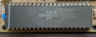
I found another bad UART which does NOT work - this seems to be a different manufacturer, but same designation "CDP6402CE":

Bad2_UART.jpg


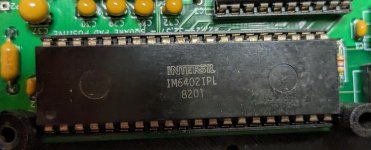
The two good working UARTs which do not cause the front panel to freeze are:

Good_UART.jpg

Good2_UART.jpg

I hope this helps others building Hideehoo's front panel. Stick with Intersil and Harris versions of the UART on the SBC6120-RBC board.
 
If you can take some acetone to the tops of the suspect packages and see if anything comes off onto a paper towel, that is a good sign of a counterfeit. If you can get photos of the bottom side as well, that may help determine it, too.
 
If you can take some acetone to the tops of the suspect packages and see if anything comes off onto a paper towel, that is a good sign of a counterfeit. If you can get photos of the bottom side as well, that may help determine it, too.

I doubt that the problematic UARTs are counterfeit. More likely they have been independently implemented by other manufacturers and are meant to be compatible, but are not quite a 100% match possibly because of some under-documented feature of the original. They work fine as UARTs. Only when you fit a FP6120 and run the 4 word count program will you see the problem.

Nothing came off when I tried rubbing acetone on 3 of them.

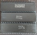
Here are photos of the backs:

PXL_20240518_030049102.jpg

Other than the word "Singapore" none of it means anything to me.
 
@hideehoo The DesignSpark Mechanical project file (“SBC6120-RBC Front Panel Case.rsdocx”) in your sbc6120-mini-front-panel GIThub repository has only the unused “Knob”, but not the “Rotary Knob Adapter” design. The “Rotary Knob Adapter” STL is there, but not in the “.rsdocx”.

I suspect you did the “Rotary Knob Adapter” as a separate “.rxdocx” project and then created the STL from it which is in your GIThub repository.

Could you please make the “.rxdocx” for the “Rotary Knob Adapter” available?

Thanks for having created this mini front panel. I am having a lot of fun with it.
 
I sliced the modified case parts (bottom plate and top case) in PrusaSlicer and overnight attempted a PLA print of the bottom plate with my Creality Ender 5.

Today morning it was almost "finished", but it printed about 50% in the air without extruding any filament. I assume somehow the nozzle got blocked at about 50%. Why is anybody's guess.

I think these 3D printers are just annoying toys requiring infinite experimentation and patience to fine-tune and modify to get poor results nevertheless. I came to the conclusion that hobby grade 3D printers are ideal for someone who's primary hobby is 3D printing.

I am interested in the hardware and software of old computers and would like to spend my time on them, not exploring the unpredictable world of 3D printing.

3D printing should be just a tool to occasionally get some parts made or repaired. None of my other tools require this level of experimentation and fine-tuning and still produce poor results or complete failures like my print attempt last night.

Maybe back in 2019 I just bought the wrong 3D printer, but after many upgrades to make it usable it still doesn't reliably produce quality prints. It was sitting unused on a shelf for the past few years and I regret wasting my time and money on it.

I briefly considered buying the highly recommended "Bambu Lab P1S" 3D printer at A$1459.00 but fortunately my sanity returned before I pushed the "buy" button. The P1S is meant to work out of the box and produce quality prints at high speed, but I don't believe the hype.

I may need a 3D printed part once or twice a year, so getting stuff professionally printed by JLCPCB makes much more sense and is more cost effective than to continue with these toy printers.

Sorry for the rant.

In a fit of insanity (triggered by an amazing 2nd anniversary sale price) I bought myself a Bambu Lab P1S (without the AMS - I don't need multi-color).
I can only say - WOW!
With this 3D printer it is effortless to print really good quality parts - fast and right out of the box.
The sale finishes on July 5.
So please ignore my previous rant. It is possible to print professional quality 3D parts at home with the right gear. My old Ender 5 was just an annoying toy.
I had a feeling you would be happy with a more capable unit. Congrats on the purchase! For me it was a tossup between Bambu P1S and Prusa Mk4. Then I started reading support (or lack thereof) stories about Bambu Labs. That and the fact that Prusa is all open source tipped the scales.
 
It was nice meeting you and your son at the VCF Midwest this past weekend.

I'm Mike the PDP-8/E guy. I bought one of your full SBC6120 kits (SBC6120 and front panel) at the show and I have a few questions?

What is the program necessary for the two PALs on the front panel (U7 & U13)?

Print out six copies of the M3 x 15.6mm Standoff if you are using the 2mm high rubber inserts on top of them, or use the M3 x 17.6mm Standoff if you are not.
What is the "TS-2.7 Option" What rubber inserts and why would you or would you not use them?
What is the part # of the 2mm rubber insert?

I presume I need to print 3 slide switch adapters?
The BOM calls SW22, SW23 and SW24 "Connector_PinHeader_2.54mm:pinHeader_1x03_P2.54mm_Vertical" What is the part # for the slide switch

The miscellaneous parts table lists three parts. The DB9 to IDC cable is included in the kit however the 5.5 x 2.1mm DC Input Jack for 8mm Hole and IDE to CF Adapter are not. Is this true? Or do I need a second DB9 to IDC cable?

Is there any way to use an SD card or micro SD card instead of compatriot flash?

Where can I find the images for the compact flash card?

Are these images compatible with the SiMH RK05 image files used on the PdDP-8/I?

Thank you,

Mike
 
It was nice meeting you and your son at the VCF Midwest this past weekend.

I'm Mike the PDP-8/E guy. I bought one of your full SBC6120 kits (SBC6120 and front panel) at the show and I have a few questions?

What is the program necessary for the two PALs on the front panel (U7 & U13)?

They're in https://github.com/djtersteegc/sbc6120-mini-front-panel/tree/main/Original STG FP6120 Files/pld It's a copy of the original files from Spare Time Gizmo's project archive.

What is the "TS-2.7 Option" What rubber inserts and why would you or would you not use them?
What is the part # of the 2mm rubber insert?

I used these rubber bumpers, https://www.aliexpress.us/item/3256805089368820.html

I presume I need to print 3 slide switch adapters?

Yep, https://github.com/djtersteegc/sbc6120-mini-front-panel/blob/main/3D/STL/Slide Switch.stl

The BOM calls SW22, SW23 and SW24 "Connector_PinHeader_2.54mm:pinHeader_1x03_P2.54mm_Vertical" What is the part # for the slide switch

It's the standard 2.54mm spaced right angle ones you find on Ali or eBay, for example, https://www.aliexpress.us/item/2251832665517359.html

The miscellaneous parts table lists three parts. The DB9 to IDC cable is included in the kit however the 5.5 x 2.1mm DC Input Jack for 8mm Hole and IDE to CF Adapter are not. Is this true? Or do I need a second DB9 to IDC cable?

IDC to DB9 cable in the SBC6120 kit will work fine, just need to shorten and rewire on the DB9 side depending on what terminal serial cable you are using (straight through or null modem).

Power Jack - https://www.aliexpress.us/item/2255801022148508.html

CF adapter - https://www.aliexpress.us/item/3256804514420229.html


Is there any way to use an SD card or micro SD card instead of compatriot flash?

Probably with something like this and some additional cabling, https://www.aliexpress.us/item/3256806600384006.html, but it's not going to fit into the current case design and end up being more expensive then just finding a nice used CF card. I being using the WD Silicon Drive models in mine and they seem to work well.

Where can I find the images for the compact flash card?

There's some CF card images on the RBC page for the SBC6120 project. https://www.retrobrewcomputers.org/doku.php?id=boards:sbc:sbc6120-rbc-edition:start

Are these images compatible with the SiMH RK05 image files used on the PdDP-8/I?

No idea, but there instructions for image creation on the same RBC page above. I would love to have premade images of Steve's Deep Thoughts and Lights Out program with his custom boot sector that would allow for simple loading of them via the front panel. On my to do project list someday to sit down and figure out how to do it for the SBC6120.


Thank you,

Mike

Good luck with the build!
 
Back
Top