• Please review our updated Terms and Rules here

Seeking header pin size recommendation

gottjoe

Member
Joined
Feb 19, 2023
Messages
10
Location
Yucaipa, CA
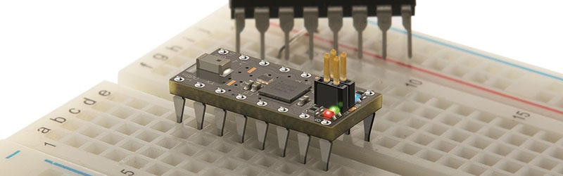
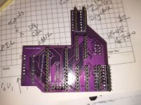
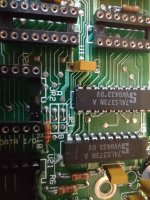
A few days ago I built a DRAM Arduino 4164 & 41256 Memory Chip Tester (it works!), and a PLA20V8 Commodore 64 PLA Replacement solution. Both projects required header pins. I used 2.54mm for both. They work great for the Arduino connection (which is what they are designed for), but somewhat damage the sockets on a Commodore 64 for the PLA replacement. I had to crimp the original PLA chip pins inward to get the chip to make contact with the socket after I tested the PLA20V8 solution (which works great). I want to build more PLA20V8's, but I need a better header pin size. Please provide recommendations for something that has worked for you.

Any help is appreciated.

Joe
 
This is a common problem. If you measure a standard IC pin, across one axis it is about 0.5mm wide and across its flat about 0.25mm. If you fit this to a dual wipe IC socket, it only forces the two spring leaflets apart by a mere 0.25mm. If you fit the IC to a round machine pin socket at worst on one axis it will force the contacts apart by 0.5mm. Any pin bigger than 0.5mm size on any axis is bad news for IC sockets.

For round machine pin sockets I search for round pins that are in the range of 0.45 to 0.5mm diameter. There are some from Mouser I think, but I don't have the part number on me. These don't over-stretch the socket then making it useless for an IC later.

If the adapter is to go into a dual wipe IC socket, there are flat IC like pins available. The source of these has been posted on the forum before, I'm just not sure where right now.
 
You can stack dual wipe sockets. So you can shove machine pins, header pins, whatever into an extra "sacrificial" socket, then plug that socket into your original board without damage.
 
'course next thing will be people bitching about their price. whatever...
OK, I am house poor right now, but I have some projects I need pins for, and yea I had the standard round ones for testing but I don't like for daily use projects because of the damage they can do to sockets, and the flats just suck because of how easy they bend, but $18 for 200 of them? Yea they are a bit pricey, you you get what you pay for. Cheap and Quality are generally mutually exclusive. I for one am someone to pay for good quality stuff. Yea I got boxes of cheap pins for little test products, but when I need an Ardrino Nano or a Pi Pico for something I plan on using a lot, like a XUM1541, I want quality stuff. Hardware is like software, garbage in, garbage out. Thank you for the link.
 
Ebay usually has some cheap Chinese male-male headers. One side (the longer side) is thinner than the other and goes nicely into machine-pin sockets without stressing them. I suspect they'll also work for dual-wipe type sockets. If you need measurements, I've got a bunch here and can provide them.
Another option is to use a DIP plug header; many of these have flat contacts.
For the m-m header example, see here.
 
The smaller diameter Gold plated brass pins are made by Mill-Max.

These are 0.51mm diameter.


You can fit these into both round machine pin IC sockets , or dual wipe without any significant damage to the IC socket. Flat pins are probably better for the dual wipe socket case.

I'm sure there was somebody making adapters who had found a source of flat pins that would mount along a pcb edge, these are ideal for interfacing with dual wipe IC sockets.

I had a problem a while back where I had to make some custom connectors for a pcb. The problem was that the manufacturers had soldered ribbon cable, into pcb holes that were plated through and had an internal diameter of just 0.6mm.

To make a plug and socket assembly I fitted the pcb with some 0.55mm diameter gold plated round pin headers (these came from ebay). Then I cut up some round machine pin IC sockets to make the female plug. It is shown on page 4 and 5 of this article:


0.55mm diameter is as big as should be fitted to round machine pin IC socket. In the case of the above problem though, an IC pin will not be inserted into these sockets again, so it is of less concern.
 
Last edited:
I had a project recently where I had to interconnect a daughter board with a PCB... The only reliable solution I could get involved machine pin headers on the daughterboard and replacing the sockets on the main PCB with machined round sockets l.
 

Attachments

  • IMG_20230922_133654255.jpg
    IMG_20230922_133654255.jpg
    3.5 MB · Views: 4
  • IMG_20230922_133629118.jpg
    IMG_20230922_133629118.jpg
    348 KB · Views: 4
Thank you all for your input. I did order some header pins from the provided ebay link. I'll test those out to see how they work, after they arrive.

Joe
 
Just for reference, here's a shot of the Chinese headers:
2023-10-16-093449.jpg
In years past, I've used thin beryllium-copper wire as well as sterling silver 22 gauge pins. I don't recommend the latter, as they're rather soft and bend easily as well as being expensive. You use what you can get, however.
 
Back
Top