• Please review our updated Terms and Rules here

Superbrain QD repair

Oh again! I found the superbrain CP/M floppy I Dave'd up last time I was saving NEC APC floppies to imagedisk. I cleaned the heads on the best of my drives. No response when the floppy is inserted but at least it doesn't tear up the disk surface in the slightest.
 
Yes. I think the one I had has good RAM. It is just the glue logic that's broken I think. I couldn't get to the bottom of it.

Check the voltages round the RAM chips. I had one machine with a broken tantalum capacitor that shorted the 12v rail (the tants are between the memory banks on the right hand column of chips, they are black and look like diodes).

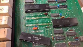
For the stuck address line, try removing the big chips first. I had a similar problem on with the KR3600 chip (keyboard encoder) on mine; it was dragging all the data lines low.

You really need a Z80 ICE to test this. You can run RAM tests with the chips in situ, and check the ROM is good (actually disassemble it in situ, single step, etc). Some understanding of the ROM/RAM paging is useful; for example, at boot up, the ROM is paged in so you have no RAM at 0000h. You can see (with an ICE) that the first thing the ROM does is copy 400h bytes from 0400h to C000h, this is the boot code which it subsequently jumps to. So check Bank 3 (C000-FFFF) is OK first (top row of RAM chips).

Code:
;	MAIN CPU CODE... SYSTEM INITIALIZATION.
;	COPY ROM 0400 CODE TO C000, THEN JP C006
;
L0013:	LD	HL,00400H	; 0013
	LD	DE,0C000H	; 0016
	LD	BC,00400H	; 0019
	LDIR			; 001C
	JP	0C006H		; 001E

The Superbrain uses the PPI chip to control memory page switching. There are two operations: ROM/RAM at 0000H and CPU1/CPU2 RAM at C000 (So-called "tri state buffer" which is used to transfer disk sector data from CPU2 to CPU1 and back again. Refer to the "techinfo.pdf" document on Dave Dunfield's site: http://www.classiccmp.org/dunfield/supbrain/ page 19. It shows the PPI port C and lines that switch the memory about. When the machine boots, you should have bank 0 as ROM and banks 1-3 as RAM. For example, after copying boot code to RAM, one of the first things the RAM-copied code does is switching ROM at 0000h for RAM using a sequence LD A,B2h then OUT 6Ah,A. If you match the bit pattern of B2h with the description on page 19 you can see what the effect of the OUT instruction will be.

If you have a problem with the glue logic, it is likely to be the paging circuit, which is in the bottom left of the Superbrain I schematic diagram, or the CAS/RAS mux circuits.
 
Thanks for the pointers Jon, ill have a read of the techinfo download a bit later.

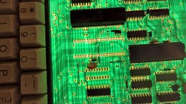
I tried removing the keyboard driver chip:

WP_20190130_10_13_00_Pro_LI.jpg

WP_20190130_10_13_20_Pro_LI.jpg

No go though, still has the short on the data bus.
 
Oh that is very neat desoldering, well done. I know you have the Duratool station but you did well there!

Take out all the socketed ICs and retest. There is a process of elimination to be followed here I'm afraid. To check the memory, terfer to the techinfo PDF where it describes the RAM test program. There is an ASCII diagram that says which DRAM chip is responsible for which data line. If it's D3 that's stuck, take the 4th DRAM from the right out (of each bank, testing the line each time).


You might be better off working on the other board (the one you sent me) as it has no shorts. In fact, it gets as far as copying the boot code to RAM (whereupon it all gets corrupted).
 
Soldering - one of the few things I'm good at!

I have done as you suggested - started on the board I sent you - and look!!

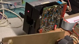
WP_20190130_14_35_39_Pro_LI.jpg

Not just a floppy drive light but one that responds to the keyboard! When you press the reset keys, the light goes out until you let go of the keys. That's got to mean something!!

The drive motor doesn't spin but this must be some sort of progress?

All I did was lift up all the 10u caps around the RAM - I noticed a low ohm reading between ground and 5v which is gone if you remove those caps.

Am I correct in thinking that the + end of the cap should always be on the +supply rail and the - side (the flat end) should always be on the ground rail? I was probing the different supply rails on a continuity/low ohm test around the RAM and it looks to me like some of those caps are the wrong way round - the bullet end + is going to a 0V rail?
 
Not necessarily. It depends on which rail it is connected to - the -5v rail would have the +ve end connected to 0V because that is the direction of the voltage potential. If you want to check the orientation of the tantalum caps, compare the two boards you have. I consider it highly unlikely that any are fitted incorrectly.

Drive motor not spinning: I assume you checked the 12v rail of the PSU and connected power to the drive. A Superbrain runs the drive motor all the time, so it should start turning at power up, unless it's been modified. A common fix was to disconnect the "motor on" line at the drive and use the drive select signal to turn the motor on. Otherwise, the main board has the motor on signal hardwired. You can check this, it is pin 16 on the drive interface J3 and it will be fixed to logic 0 via a gate on Z71 (bottom right hand side of the schematic, just above where it says "INTERTEC DATA SYSTEMS"). If you find that pin 16 is connected to Z71 pin 10 then it hasn't been modded and the motor should spin when power is applied (to the drive and main board).

I've done this mod to my Superbrain, exclusively on the drive PCB. The way I blanked off the motor on signal was to lay Sellotape over the corresponding track on the drive's edge connector because I didn't want to cut any tracks on the SB's main board. So check your drive for this mod. There's another tell tale on the drive (connection between its drive select and motor on lines) that indicates it's been modded, but your symptoms suggest one is modded but not the other. Unless the FDC is suspect, of course.

I am sorry to have to tell you this, but the red reset keys are not connected to the keyboard controller. They are acting as switches wired in series, directly connected to the reset circuits. So they always work, even if the keyboard controller is dead or removed. If you look at the schematic, you can see them just above the KR3600 keyboard controller (over on the right hand side). They're wired in series and one end goes to 0V, the other goes to the various reset circuits.

Regarding the capacitors, check which one is shorted out (it's a common failure point) and replace it. You need a tantalum capacitor, 10uF 20v, preferably axial (that is, with the pins coming out on opposite sides). Refit the others (they're there for a reason...). You can run with one or two missing while you wait for supplies.

Your drive does not appear to have a terminator. It needs one if it is the only drive fitted (a terminator looks like an IC but is actually a row of resistors that go across the drive data lines). It goes in that blank IC socket on the drive PCB. Look on the other drive, you will probably see it fitted. By the way, missing the terminator won't prevent the motor stating up but it might interfere with data transfers.
 
Last edited:
By the way, my testing on that board didn't indicate there was a shorted out capacitor, so it must have failed very recently. I was seeing inconsistent memory reads but that might have been a problem with my ICE (it was doing this on my SB II board, which I subsequently found out worked perfectly). Do you have some independent means of testing the drive? Plug into another computer, perhaps just to see if it spins up?
 
It may just be my wonky testing! Any idea what vloss is acceptable with one of those tant caps? My component tester reads 1% Vloss with one on the board I tested. I bought some new ones off ebay - they test at 0.4% Vloss

The drive I have plugged into the board I sent to you spins up fine in the other board. Its also a drive I used ok a year or so ago to create a Superbrain boot disk with.

I have just dragged my imaging PC out of the cellar - I can re test it but I do know the motor spins constantly when its plugged into the other board.

Oh, the ABI component tester seems to work - sort of! I think the contacts in the ZIF sockets are quite dirty - just found my Dremel and mini wire brush tool too. It failed a load of chips, giving random readings as to which pin the fault was on. It did also pass a couple of 74LS series ICs so hopefully it just wants its contacts cleaning. Gives better results in one of the ZIF sockets rather than the others.
 
OK, so the drive motor is OK and recognising the motor on line when connected to SB 2 (let's call the board you sent me SB 1).

Does the drive activity light come on when connected to SB 1? What about SB 2?

I know nothing of "Vloss", but if a tant is shorted out (and they are known for this failure mode), it must be pulled and / or replaced.

Do the test on the motor on line of SB 1. See if it has continuity with Z71 pin 10. Use a simple logic probe to see if Z71 pin 10 is logic high or low (should be low).
 
Somewhere, I have a terminating resistor pack. Just not sure where! There are none on any of those 5.25 drives, I probably used it elsewhere. I guess I could make one if I google the value of the resistors inside - or just wait for eBay to send one. I could also rob one off my NEC APC / IMS 8000. Don't like doing that though.
 
With SB1 (I sent you) I now get the LED coming on permanently - goes off when reset keys are pressed.
Before yesterday, You would see the LED give the briefest flash and the disk friction spindle would move a fraction.

With SB2 (Original board that came with SB, has D3 short) The motor spins continuously but no LED activity.

It will be tomorrow evening before further testing can happen - I start work at 3pm today and then it will be family stuff all day tomorrow.

Also need to find the proper floppy drive cable - not sure the one I have connected now was for the SB. May even be for an MFM HD now I think about it!! :(
 
Big improvement with the chip tester - just dremmelled the ZIF sockets and its giving consistent results for ICs I know are good. Search function works too for unknow ICs :)
 
Nice. Floppy cable is a standard 34 way IDC female (at the SB end) to 34 way IDC edge connector (at the drive end). If your cable fits both ends it should be OK. Just remember that Pin 1 is furthest away from the keyboard on the Superbrain and nearest the edge oif the board on the floppy drive. If you connect it back to front, the activity light will be on all the time irrespective of what the SB is doing.

Markings on my terminator are 16-1-151 (16 pins, isolated, 150 ohms, according to a Bourne datasheet I just read). It is also bright blue plastic and has a date code of 89/14 FWIW.
 
Am I still stabbing in the dark? Probably!

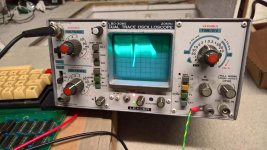
WP_20190203_23_42_47_Pro_LI.jpg

I've replaced two caps on the 5v lines above the top RAM bank.

I've re soldered all the other capacitors I had previously removed.

On probing around the 74LS221 chip on the psu board and the video inputs to the vdu driver board, I have waveforms on my oscilloscope.


OK, so the drive motor is OK and recognising the motor on line when connected to SB 2 (let's call the board you sent me SB 1).

Does the drive activity light come on when connected to SB 1? What about SB 2?

I know nothing of "Vloss", but if a tant is shorted out (and they are known for this failure mode), it must be pulled and / or replaced.

Do the test on the motor on line of SB 1. See if it has continuity with Z71 pin 10. Use a simple logic probe to see if Z71 pin 10 is logic high or low (should be low).

I will try as you suggest - test continuity of motor on line to Z71 tomorrow morning.
 
Hi Alan

The Superbrain main board outputs HSYNC, CSYNC and VIDEO (luminance) signals to the CRT board. The sync pulses look like this: https://stardot.org.uk/forums/viewtopic.php?f=45&t=16316&start=60#p225770.

I would recommend you probe for these signals at the video chip rather than probing under the edge connector. Do any of your probes have clips or are they all pointy?

If you suspect your CRT or video board is not working, you can build a small circuit to combine all three signals into a composite sync, then plug that into a monitor or TV.

I use the Ver 0.5 circuit shown on this post: https://stardot.org.uk/forums/viewtopic.php?p=46253#p46253 connected to my own composite circuit shown here https://stardot.org.uk/forums/download/file.php?id=43012&mode=view to get composite out of the Superbrain II. If you review the whole thread (starts here: https://stardot.org.uk/forums/viewtopic.php?f=45&t=16316 ) then you can see pictures of the board I made.

You have an ICE I believe, so start the SB up and see if you can examine the memory at F800h, that's where the screen RAM starts and you might see a boot prompt there. This is how I determined my SB II board was working.
 
Just tried reading from F800 to FFFF - it just comes up with fails.
Any attempt to probe memory above ROM results in fails - both boards. Not sure if my ICE doesn't like the SB?
 
Oh, i think i just fooled myself into thinking SB1 is booting! I turned on the MX (multiplex) jumper on my A:drive. Wondered if treating it like a single drive system would make some difference (for no particular reason) with MX on, the drive spins up and you get head activity when closing the floppy door on a boot disk/pressing the reset keys. Probably a false positive/feature of MX being on?
 
Back
Top