• Please review our updated Terms and Rules here

Superbrain QD repair

Alan, it sounds like it is booting or at least, loading the boot tracks. Check the screen is on. Check the brightness control, you should be able to turn it up enough to see the lines even if there is no text being displayed. You could also try the other tests I mentioned (CTRL-G then RETURN - should beep).
 
Hi Jon - ill certainly try the beep test - the screen is dead except for heater glow. No HT. I've swapped the flyback transformer for a spare, no sign of high voltage. I've fiddled with the brightness control too.

What is the minimum in terms of signals that the vdu board needs? Some of the video lines go to that chip on the psu board. I wonder if that is a place to test?
 
No, check the 15v supply line first. Test the connections to the video board using a multimeter (continuity). It needs GND, power, HSYNC, VSYNC and Video (Luminance). Also there are three wires that connect to the brightness control on the back panel. It is all on the schematic. Make sure they are all making good contact. Then remove and check the video board solder side for any dry or loose joints especially round the connections to the flyback. For example: https://stardot.org.uk/forums/download/file.php?id=29948&mode=view - cracked solder joints on
the wires going to my Superbrain LOPT. See how the solder itself is cracked? That was leading to an intermittent loss of picture.

I think you may need to build the video circuit, at least for testing. I can help with that, I have composite video boards spare, but you'll have to build the sync combiner to generate CSYNC yourself. Again, I can help.

Try the ^G test. If it beeps, try the DIR test. If there is disk activity you are up and running, and just need a video solution.
 
Last edited:
Ok - no beep from a ctrl G nothing from DIR CR

I have re wired / resoldered all the vdu cabling going from the psu to the vdu board, including removing/resoldering the brightness pot.
Traced all lines and it looks good
Getting correct 15v at 4th pin from the right om the vdu connector.
IC Z56 is testing faulty at pin 6 - it happened to be socketed. It is between Z54s h sync and the h sync output. I will also test z57 tomorrow morning.
 
Last edited:
OK, so it isn't booting fully to CP/M. Darn it.

Might be worth putting your 'scope on the HSYNC. VSYNC and Video. Or the logic probe (you can see if they are stuck or pulsing). If stuck, trace back and you will no doubt locate an IC with a stuck gate. This is how I fixed my PET...
 
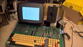
Ok, bit more progress - I have a picture!

This is after replacing Z56 (7486) and the chip on the PSU (74LS221)

You now have to press the reset keys after power on to get the floppy drive light and boot activity.

Nothing legible on the screen, just those vertical white bars on the left and the faintest block shaped flicker up and down the left of the screen when reset is pressed.

WP_20190209_11_38_26_Pro_LI.jpg
 
Something else must have changed because if I put the original Z56 chip back, the crt makes crazy noises, like HV going crazy inside the crt or something.
 
I've tried different CRT chips and character generation chips plus PPI chips. All have the same result so I assume they are all working ICs I have as spares? Also tried all 4 ROMs but they must all be blank. I only get disk reads and video with the EEPROM. Maybe its worth trying a different ROM version too?

Next plan is to socket that keyboard encoder chip - just because I may as well! Oh, and test Z57 as that is tied into the video output after the crt chip. Not getting much on the scope at pin 1 of the CRT chip which is the Video out pin. I seem to have Horizontal and Vertical but no video?
 
Oops..

Obviously you will have swapped Z56 back to the "sane" one. Have you attempted without the boot disk? We're looking for the "Insert diskette" message from the first stage bootloader.

Other things to check: The character generator and VDP chips. Try swapping them out with the other board or some of your spares.
 
That's what I get on the screen regardless of the boot disk. Power on, press red buttons (with drive door open) and that screen comes up. I've swapped the various socketed chips.

Believe me, I'm waiting on that Insert Boot Disk message!

It would be pretty amazing to get this board working. I've had it most of my life!
 
Beat me to it.

Also try probing around Z55, the shift register that feeds the character generator. We should have activity on its input and outputs. Check Z56 pins 11, 13 and 8 for pulsing, and Z57 pin 6 for pulsing. This is the video signal, if it's stuck you would get a white screen (or black, depends on which way its stuck).
 
Ok Jon, thanks for that. Have to pause for a bit now as family matters press. I'll report back later ��
 
I've got pulsing on all inputs and outputs on Z55

Z56 pin 8 and 11 both pulsing. Pin 13 is high.

Z57 pin 6 is pulsing.
 
That is the video (luminance) output from the CRT8002. Put a 'scope on it. I'll check mine, but I don't think it should be high. (Edit: Yes, should be pulsing. This is why you have a full on white screen I think!)

Anyway, speaking of "having a bad day..."

https://youtu.be/JCmyvacGTCQ

(wait for the upload to complete)

It was all working fine until I started filming. What's actually happened is the directory tracks aren't getting read properly for some reason. If I format the disk and start writing stuff to it, all is well; but the moment I power cycle the machine it all goes to pot, because the in-memory buffers are lost.
 
Last edited:
So near yet so nearly there? Superbrain plus hard drive - the ultimate! All it needs then is my Pixelplotter unit on one side, an S100 adapter on the other, a psu upgrade...

Let's get to a working SB first...

On pin 15 of the main ribbon cable between the logic board and psu, I have a signal of some sort according to my scope. That's the video line according to the diagram.

I also socketed the keyboard chip. Only thing I discovered is that I have one working chip out of the three. With the other two, I loose the drive activity.

One thing I did discover - I tried an AMD PPI chip. If I press on its lower end, I can make a faint dark.block cursor appear on the screen. It moves back and forth along the top left on a hard reset - as if the insert disk' message is cycling with the reset keys being pressed. Pressing on the PPI chip also makes that cursor jump around the screen from top to bottom under the boot disk message location.

Wonder if it's worth replacing the PPI socket or looking for bad joints under there?

Also discovered only one of my VDU driver boards works. Need to recap it. The picture may improve?
 
Definitely need to recap. Picture began to shrink in width as smoke poured out of an electrolytic! Pause for ebay again!
 
Ah, you let out the magic smoke! :D

Occupational hazard, I'm afraid.

Definitely replace the PPI socket. It is clear there's a bad connection there. I had the same thing with my CPU socket; it's worn out and only works with the uIDE Z80 shim installed. Check the other sockets too.

For the PSU upgrade, buy a Meanwell 12v power supply. Meanwell = "good quality brand", if it is genuine. Don't use generic cheapo PSUs from China because they have a habit of blowing up. Connect the Meanwell PSU to the disk drives' 12v line, disconnecting it from the Intertec PSU, and connect the Meanwell -ve line to the ground on the Intertec PSU.

This takes a lot of load off the marginal Intertec PSU and since fitting one to my machine I have had zero problems. I actually did mine to resolve screen picture glitches each time a floppy was accessed, as I'd implemented the driver motor control mod so each time a motor started there was a bit too much current drawn, which upset the monitor.

Anyway, speaking of uIDE..

Take 2: https://youtu.be/y-gY0S2aVvs

..and, because things never go as planned..

Take 3: https://youtu.be/hBrnUB8LXkE

:D
 
Getting closer Jon - just another bug!

Update on the repair. I've ordered £10 worth of electrolytic caps for the VDU driver board. The picture I have is not filling the width of the screen because of the cap that released the smoke. As it let off, the screen shrank further. Hopefully the picture will improve in stability and quality if i get rid of all the crusty 40 year old electrolytic's off that board.

I've also had a shift change at work so i no longer have mornings free - further work may be confined to the weekend, so Friday/Saturday.
 
Back
Top