• Please review our updated Terms and Rules here

Tektronix 4010 restoration

Thank you Dave. YANA is generated on board TC-2. If I remove the board the vertical line does not show up on power up.
I probed YANA on mother board pin /P and see a saw tooth pattern (click to see full size):
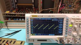
IMG_20230608_234540696.jpg

I also see that the 74139 latches DN signal is clocked with short 500 ns pulses repeated at 4.8 kHz.
 
So not the deflection amplifier board then...

Is that on pin 4 (UP), pin 5 (DOWN) or pin 11 (LD).

I guess not on pins 5 or 11 - so it must be pin 10 (UP). Is that the case?

Dave
 
The saw tooth is on pin /P on the motherboard after the DAC.

The 500 ns pulses repeated at 4.8 kHz are on pin 5 (DOWN).

Edit: Pin 4 (UP) is High, Pin 11 (LD) is Low - both are static.
 
I tossed a coin - and guessed wrong :)!

So that takes us back to board TC-1; and in particularly U67 (7401) and U88 (7475). A constant /DOWN here would be synonymous with a constant /LF input to U88 pin 7 - or somewhere else down the chain...

There is a 1.22 MHz clock that effectively feeds into the U67 NAND package.

Incidentally, I am on PDF page 201 of 251 of document https://bitsavers.org/pdf/tektronix/401x/070-1183-01_Rev_B_4010_Maintenance_Manual_Apr_1976.pdf.

Dave
 
I am looking at the same manual - until now page 203 (TC-2).

Trying to look at the TC-1 board is getting much harder.
To probe signals on the TC-2 board I removed the Comms board to the right (or above in my case as I have the pedestal laying on its side), and I was able to directly probe the signals while the 4010 was powered.
For TC-1 I would need an extender board which I don't have otherwise probing will involve powering off, removing the TC-1 PCB, soldering a wire on and reinserting TC-1 and powering on. Not impossible, but painfully slow.

Edit: of course I could just remove TC-2, but that may have some impact the behaviour of TC-1.
 
Ah, your last post came in while I was writing this... It might shed some light on your problem?

Before we start chasing our tail...

Can you just check U63 (74154) 4:16 decoder. This decodes for a specific control character (e.g. /LF, /CR, /BEL, etc.).

Do you actually have the interface card in or not? If not, I suspect the inputs to the 74154 may be floating...

Dave
 
The Comms board was removed while I was probing, but with it in or out makes no difference to the vertical line.
U63 on TC-1 is tricky to get to. I will try and remove TC-2 (and Comms).
 
Hmmm - all control character signals (/SO, /SI, /FF, /CR, /LF, etc) on pins 1 - 8 of U415 are High (de-asserted).
Strangely even if I press CR with the terminal in Local Mode I don't see a change on pin 3 (/CR) of U425 (i.e. 74154).
 
I assume this is with the interface, TC-1 and TC-2 boards in?

Perhaps we ought to start off with something much more simple - the keyboard - and work our way from there!

That keyboard schematic looks very familiar! I see there are two in the manual. Which is yours?

Dave
 
Nope - TC1 was in and TC2 and Comms was out.
I just probed /CTRL_CHAR_STROBE pin 19 of U415 and it never toggles if I press CR.
I don't yet understand the interactions of TC1 and TC2, so my probing with TC2 removed may not be valid.
 
Doesn't the keyboard unit connect to TC-2 via connectors J20 and J21 - so if you are checking on TC-1 by poking keys on the keyboard then you will also require TC-2 installed?

The keyboard strobe should appear on J21 pin 2 with the data lines (corresponding to the keypress) on the other J20 and J21 pins.

Dave
 
I have to read more of the manual. You are probably right about the keyboard strobe coming via J21, but it is almost 2 am and my brain is fading.
I will continue after some sleep.
Thanks for your help so far.

Edit: I think I will need to find/make/borrow an extender board.
 
I just took my son out and on the way back had a thought about what time it was over at your place!

Yes, have a good sleep and then read up on the manual a bit.

I did read in the manual that you can put the TC-1, TC-2 and interface card in any order on the motherboard. However, I would NOT do that until we are more confident about the validity of the statement!

The keyboard signals go onto TC-2 and then via some multiplexer chips...

I think there is just a learning curve to go up!

Have a good sleep!

Dave
 
I have re-fitted the HV & Z-Axis board and after power-up I get a bright vertical line along the left side of the screen (and also a dimmer curved line to the right of it).
It responds to the Page keyboard press with a bright green flash which erases the screen, but immediately after the vertical line is back.
I cannot yet explain the reason for the vertical line which appears immediately after power on.
Has any Tektronix 4010 person here got any ideas about what could be causing this?
Here is a photo (click to see full size):

View attachment 1258611

Can anyone offer any advice?
The vertical line sounds like the hard copy function on the Tek 4050 computers.

If you press the Copy key on the 4050 computers with a 4631 Hard Copy Unit connected you see a bright vertical line scan across the entire screen. This beam 'reads' the phospor intensity under that line and the 4050 computer sends the analog signal to the 4050 hard copy interface connector which causes the 4631 to print all the contents of the screen on special 3M dry-silver paper.

If hard copy is a feature of the 4010 - then that circuit may be blocking any terminal function like keyboard input and character display.

It looks like the far right switch on the 4010 keyboard is labeled Make Copy:
https://legalizeadulthood.wordpress.com/2008/04/30/tektronix-4010-4051-and-4114-and-apollo-dn10000-join-the-collection/

controls.jpg


I just checked the http://www.bitsavers.org/pdf/tektronix/401x/070-1183-01_Rev_B_4010_Maintenance_Manual_Apr_1976.pdf and the 4010-1 had hard copy built-in.
 
Last edited:
I can't find the circuitry for the MAKE COPY function on a quick look. There is a signal by that name - and the manual does make reference to the function - so it does exist!

I would still try and work out what is going on - as understanding the logic will significantly help in maintaining the machine in the future. Knowledge is power!

Dave
 
Maintenance manual page 116 (6-4) at the bottom right clearly says that all boards except the "Deflection Amplifiers & Storage" board can be plugged anywhere on the "minibus". So TC-1, TC-2 and Comms board can sit anywhere except in the left-most slot (in my case with the pedestal laying on its left side that is the bottom slot).
 
I can't find the circuitry for the MAKE COPY function on a quick look. There is a signal by that name - and the manual does make reference to the function - so it does exist!

I would still try and work out what is going on - as understanding the logic will significantly help in maintaining the machine in the future. Knowledge is power!

Dave
Hard Copy Block Diagram is on maintenance manual pdf page 189.
- note below Make Copy signal indicates circuitry is on Display Amplifier and Storage Board

Pdf page 190 has board connectors and wiring diagram with Hard Copy Amplifier board at top right corner.
Pdf page 191 Mother Board wiring shows discrete circuit diagram for Make Copy signal
 
Back
Top