• Please review our updated Terms and Rules here

Tektronix 4010 restoration

Minibus signal /Make_Copy is showing 500 ns pulses repeating at 76.9 kHz. This is independent of the position of the momentary "Make Copy" switch.

Edit: the above is incorrect. Signal MAKE_COPY nicely follows the momentary "Make Copy" switch. Earlier I counted from the wrong side of the minibus.
 
Last edited:
I am back at trying to figure out what causes the vertical line.
On page 203 (top-left) there is U369 (74193) which is an up/down counter.
I see that the minibus /DOWN signal is toggling at approx 76.9 kHz and feeds into pin 5 of U369 labelled DN (the datasheet calls it UP).
I never see pin 11 labelled LD toggling.
I found 3 places where /DOWN is generated:
  • one is on TC-1 page 197 (top-right) from pin 10 of U351 (7401 NAND OC output), but I don't see corresponding signals on the inputs (pin 8 & 9) of the NAND gate.
  • the other is TC-2 page 203 (upper-left) from pin 4 of U341 (7401 as above), but while I see the 614 kHz on the corresponding input pin 5, I don't see any activity on pin 6.
  • finally there is TC-2 page 205 (lower-right) from pin 10 of U341 (7401 as above) and see input pin 8 being high and activity on input pin 9 which is the inverse of the output pin 10 feeding into /DOWN. So clearly this is the path where the /DOWN signal is being generated.
Tomorrow I will try to understand the logic around U31A (74123 mono-flop) on TC-2 page 205 where pin 13 feeds pin 9 of U341 which is the source of the continuous /DOWN running at 76.9 kHz.
There is a 614 kHz clock which is divided by 8 yielding the 76.9 kHz of /DOWN, but there is some other magic happening that feeds into pin 2 of U31A. This path is complex and I don't understand it yet. It may be the cross-hair generation, but it may be something completely different.
The revision of my TC-2 is 12. This matters in the context of the cross-hair generation described on pages 153-155.
 
Last edited:
Made some headway. Over to you when you wake up and I am asleep!

Yes, the cursor appears to be 'accidentally' enabled.

The key description appears to be on page 6-24 (PDF page 136) and figure 6-2 page 6-25 (PDF page 137).

For this to be active, /CURSE should be active. I am not sure whether this is active LOW though! I think this should be active HIGH. With this signal LOW, the flip flop U229B will be held in RESET mode (and this may account for why we are getting a vertical line rather than a crosshair cursor).

Now, there is a signal CH ENABLE (Cross Hair ENABLE). This should be LOW on a reset thus preventing U31A (the 123 monostable) from firing.

I suspect either U31A is duff, or CH ENABLE is erroneously active (HIGH) on a reset.

The /CURSE [sic] should only be activated when an <ESC> <SUB> is received.

Over to you to take some measurements...

Dave
 
I made very significant progress! :)

While tracing signals on TC-2 I noticed that /CLEAR was about 2V so not in the band of nice TTL levels.
I then tried to work out what was causing it. It could have been at the source of the signal i.e. pin 13 of U239D (7402 NOR) or alternatively some load may do some nasty thing to the signal.
Possible candidates were U141C pin 11, U109D pin 12, U239D pin 13, U309B pins 4 and 5, U301 pin 3 or U331B pin 7.
Looking at the inputs and outputs of those loading gates I thought they looked reasonable even with the dodgy /CLEAR input signal.
I then looked at the other signals around the source of /CLEAR on U239 and quickly discovered that output pin 1 had a sick 2.2V level and output pin 10 was low despite valid changing signals on its input pins 8 & 9.
Luckily Tektronix PCB assembly staff didn't go crazy with the IC pins, so while there were a little bent, my vacuum desoldering machine quickly and cleanly desoldered all pins of U239 and it popped out of the PCB with little effort.
I soldered in a 14 pin DIP socket and with my hopes high plugged in a 7402.
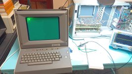
After reinstalling TC-2 and powering on and after hitting Page I saw this (click on the image to see full size):

IMG_20230610_215125445.jpg

No more vertical lines, but a very bright cursor. There keyboard (in Local mode) nicely responds to typed in characters and the cursor moves to the right but text is not visible because the screen just stores the super bright outline of the cursor.
The Return key and Line Feed key do what is expected.
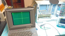
Entering ESC SUB (Ctrl-[ and Ctrl-Z) on the keyboard switches to Graphics Input (GIN) mode and show the X/Y cross-hairs.
The cross hairs correctly respond to the two wheels on the keyboard.
Here is how it looks:

IMG_20230610_215149195.jpg

I suspect that if I manage to reduce the crazy brightness, I will get readable text on the screen.
The intensity circuit is on the HV and Z-Axis board. Adjusting brightness on that board via R130 does very little.
Adjusting the brightness pots on TC-1 and TC-2 is also barely noticeable.

I will try to figure out the intensity circuit on the HV and Z-Axis board.
It is much more tricky as I am not probing in a nice controlled environment on my bench, but in the back of the display unit with lethal voltages and earth just waiting to kill me. :(
My red HV poker has a rather coarse tip and is not suitable for probing around smaller components.
 
There is trouble in the intensity circuit on the HV & Z Axis board.
The circuit expects between 173 V (normally) and 213 V (doing hard copy) feeding into the circuitry around R130 and Q37. It is only 150 V though.
The 173 V is generated via a small regulator circuit controlled by Q35 and regulated by U119 and Q115. Some of the resistors have correct markings but I read strange values in circuit but with the power supply (J61) disconnected.
For example R98 is 5k instead of 15k, R101 is 2.4k instead of 6.49k.
Tomorrow I will set this up again on my bench and rig up the necessary supply rails to test this out of the display.
Time for bed.
 
I have been struggling today with the intensity circuit on the HV & Z-Axis board.
Yesterdays suspect resistors turned out to be fine once I lifted a leg and measured then.
Sometimes there are non-obvious bits which affect your measurement while in-circuit.

Q115 is Silicon NPN transistor in TO-39 package and according to the parts list is a Texas Instruments SGC2622.
It is the power transistor used to regulate & switch between 173 V or 213 V on the HV & Z-Axis board. Unfortunately I cannot find this transistor via Google or by going directly to Bitsavers.
Any ideas where to find a datasheet for a SGC2622.

I wish Tektronix wouldn't bend the ends of pins before soldering them in.
If I don't care for the components I just cut them out with side cutters and unsolder each pin individually to preserve the PCB - this is my preferred way of removing components.
On the other hand if I am dealing with an obscure part I want to preserve or test but where I need to lift a pin or remove the component altogether for testing, then the bent pins are a major obstacle.
Trying to unbend the pin with the tip of the soldering iron in most cases means that you slip off and possibly damage tracks.
Even resistors are painful. Often component leads are remarkably stiff and resist unbending. IC pins are the most cooperative and generally can be unbent with the desoldering iron.
Is there a better/good way of dealing with these damn bent pins?
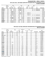
I checked the oldest Tek Semiconductor Cross Ref manual - 1982 and it lists the Tek part number cross-reference as SE7056 from Fairchild Semiconductor.
I found a link on google search to the Fairchild 1971 Transistor and Diode Condensed catalog and found the following specs:

1686531628436.png
 
As it turned part of the problem with the low voltage generated by the Intensity Control circuit on the HV & Z-Axis board was U119 which was a Tektronix uA741 op-amp which I replaced with a socketed Texas Instruments UA741.
The circuit now correctly generated approximately 175 V normally and about 225 V when /HCU_INT is pulled low. Brightness is still very high, but R130 varies the brightness voltage through a reasonable range. The brightness won't change though.
I start to suspect diode CR130 (Tektronix Part # 152-0061-00) a Tektronix special I am struggling to find any info about other than what is listed in the 4010 parts list: Silicon, 175 V 100 mA.
I searched through the nice Tektronix Common Design Parts list nikola-wan pointed me to, but didn't find this diode.
 
For an experiment I changed the bad diode CR130 (Tektronix Part # 152-0061-00) to a 1N4004 which is a very poor match, but at least it survives 400 V and 1 A.
Still no brightness control though. There are still diodes CR90, CR92 and CR94 which may be sick.
 
I dug through my parts boxes and found that UF4004 are a much better match for diodes CR130, CR90, CR92 and CR94.
It is too late tonight, but I will try and replace them tomorrow. Hopefully this will finally give me brightness control.
 
Back
Top