• Please review our updated Terms and Rules here

Tektronix 4010 restoration

Today I made some more progress with my Tek 4010.
I desoldered diodes CR90, CR92 and CR94 on the HV & Z-Axis board inside the display unit. These generate the grid voltage to control the brightness.
CR90 and CR94 tested bad.
I replaced all three diodes with UF4004 which has a Vrrm of 400 V, If of 1 A and a maximum trr of 50 ns, but a somewhat higher CT of 30 pF compared to the measured 6 pF of the original.
Today I also again replaced CR130 which tested bad yesterday and which as an experiment I replaced with a standard recovery 1N4004. It worked ok, but a UF4004 is a better choice.
After reassembly and power on I had nice control of brightness via pot R130.
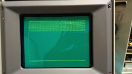
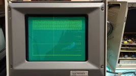
Characters typed are visible and persist. Cross-hairs are visible but don't persist (mostly) when you move them around.
Of course there are still problems:
  • After 10 characters typed the cursor backs up two characters and if you continue typing those characters are overwritten. This repeats 4 times across the screen (I typed 3 lines of "A" without and spacing).
  • After 19 characters typed the cursor jumps two characters forward. This repeats 3 times across the screen resulting in 4 columns of characters visible.
  • The X cross-hair display correctly, but the Y cross-hair shows the same type of over-type as the typed characters. This leads to persistence of the "over-typed" segments of the Y cross-hair.
  • The Y-cross hair also exhibits the skipping of segments in the same horizontal positions as the typed character line.
Clearly this is a logic problem. It looks like something like a horizontal "pixel-count" is doing something funky. More reading of the description and studying of the relevant schematics should reveal the culprit. Hopefully it is a part I have in my stock of parts or I can easily get.

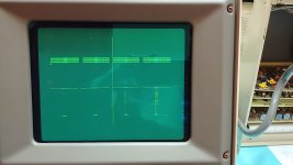
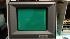
Here are some photos showing the problems (click on the thumb nails to see the full size photo):
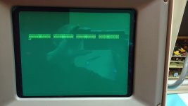
IMG_20230613_124839595.jpg

IMG_20230613_125031541.jpg
 
Hmmm - the problem has shifted a little.
After 10 characters typed the cursor backs up four characters and if you continue typing the previous characters are overwritten ... but not exactly. The characters are a little offset.
After 19 characters typed as above the cursor now jumps four characters forward.
According to the maintenance manual each character position is 14 coordinate positions (pixels) wide.
I suspect that the problem is on page 203 of the manual (TC-2 Sheet 1 of 3). Specifically around U69 (74193) and the diodes and resistor network to the right of it (implementing part of a DAC).
Unfortunately I cannot reconcile the 14 coordinate positions per character and a failure in one of the bits of the 74193 Binary Up/Down Counter.
As the counter seemingly recovers after 19 characters (it skips forward by 4 characters) it cannot be the U69 (74193) itself.
Probably after some sleep the penny drops and I can work it out. It may be as simple as one of the DAC diodes or resistors has gone short or open.
Why the problem moved from two characters back & skip to four characters back & skip is weird. It implies the two failure modes (2 versus 4) have something in common. Maybe the diode array U189?
 
I am typing here before I am thinking...

If you turn the cross-hair cursor ON and move it over the screen systematically from left to right and then top to bottom, wouldn't that test out the counter chain and DAC? What remains then must be either ahead of the counters (parallel load) or associated with the counter input stages.

Just musing...

Dave
 
...
If you turn the cross-hair cursor ON and move it over the screen systematically from left to right and then top to bottom, wouldn't that test out the counter chain and DAC? What remains then must be either ahead of the counters (parallel load) or associated with the counter input stages.
...
Indeed if you move the cross-hair left to right it exhibits similar skips as in alpha-mode. This confirms some weirdness in the part of the circuit around U69 as described above.
I wrote similar because the cross-hair skips back about 4 character positions, but when I move the cross-hair a little further to the right it skips back to where it should have been. In alpha mode it takes 9 characters types in for it to recover the correct cursor position.
I am pretty sure that this is not the 74193 itself. Maybe my "sureness" is also influenced by only having the LS version of the chips in my parts drawers which probably cannot drive the resistor network. :)
The STD TTL parts are obsolete so I would have to get them from Ebay and wait for weeks.
 
Excellent, so we think alike...

Yes, the LS part may probably upset the DAC.

Yes, it does sound like a 'bit' that is duff (but I am also guessing)...

Dave
 
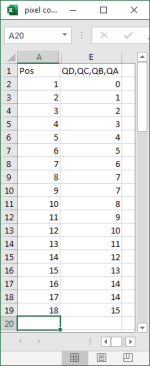
I first made a small spreadsheet to work out the expected values on U69's pins QA - QD for every character I type on the 4010:

pos-calc.png


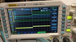
I hooked up my scope/logic-analyser to U69 (74193) pins QA, QB, QC, QD and UP.
Analog Channel 1 is hooked up to output of op-amp U92 effectively monitoring the X deflection.
QA - QD nicely count up from 0 - 7 and the X deflection voltage out of the op-amp U92 also slowly steps down.
When QA - QD increment to 8 the digital channels correctly show a value of 8 (QA, QB, QC all low and QD is high), but the X deflection voltage on the op-amp output made a big step up - the cursor went back by about 4 characters.
Here is a photo of the scope/logic-analyser when QA - QD changed to 8 and note the large step up on the yellow analog trace. This should be a small step down like with the previous 9 characters enter on the 4010.

IMG_20230614_223110492.jpg

Click on the photos to see full size.

This means that the 74193 counters work perfectly, but the diode & resistor network connected to QD is broken.
 
Hmmm - the TC-2 board layout on the Maintenance manual does not exactly match reality for a revision 12 board.
Specifically diode CR181 is not where it is shown.
Tomorrow I will check both resistor R182 and diode CR181 and hope that the problem is not in the obsolete diode array U189 (CA3039 - although there appears to be a spare diode in there).
 
More progress. Of course the problem was in a part of the DAC diode & resistor network which I don't have and is obsolete, but Ebay to the rescue.
I have order a few of the CA3039 diode arrays and hopefully have them in a week or two.

In the meantime I lifted the two legs of the faulty diode in the CA3039 diode array and after confirming the diode is faulty cut the pins and soldered in an ordinary 1N4150 fast-recover diode I have in quantity.
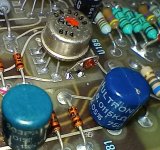
Here is a photo:

IMG_20230615_185402729.jpg

Note the precision cylindrical wire-wound resistors visible in the foreground used in the DAC on the TC-2 board.
The little 1N4150 diode fits neatly into the space left after I cut out the legs of the faulty diode in the CA3039 array.

Actually I was tempted to rip out all of the CA3039 diode arrays and replace them with discrete diodes, but to maintain authenticity I spent the money to buy the real thing.

After powering up and filling the screen I get this:

IMG_20230615_165731392.jpg

Even the cross-hairs look much better and move smoothly without skipping around, but there is still some unwanted persistence:

IMG_20230615_165835141.jpg

As always click on the image to see full size.
 
Outstanding!

Now you need some Tektronix 401x vector/text files to send to your 4010!

Check out this website - where I helped the author with grayscale files for the Textronix 4014 with Enhanced graphics option:
https://github.com/rricharz/Tek4010

there are instructions in the README on sending the vectors to a terminal using a serial interface.
I also built a PiDP-11 which emulates a PDP-11 computer and can run rricharz Tek4010 programs and send them to your 4010 terminal.


Another approach is to use the 4010 terminal with a Tektronix 4041 GPIB Test Automation Computer - see my thread:
https://forum.vcfed.org/index.php?threads/tektronix-4041-computer-from-the-early-1980s-working.76507/

I was able to connect my 4041 to my Tektronix 4052 computer and I ported Artillery and Adventure to the 4041 and used my 4052 in 4010 terminal emulation mode for those games!

I have posted lots files of Tektronix 4050 series program tapes and Tektronix 4041 program tapes I have recovered:

https://github.com/mmcgraw74/Tektronix-4051-4052-4054-Program-Files
https://github.com/mmcgraw74/Tektronix-4041-GPIB-Controller
 
Last edited:
Outstanding!

Now you need some Tektronix 401x vector/text files to send to your 4010!
...
Thank you. First I will need to go through the "Adjustments" in chapter 4 of the Maintenance manual.
The serial cable was cut off in the back of the unit, so I have not yet tried to send/receive anything via the serial port.
I am not worried about the serial stuff, because that is a relatively simple part of the system and should be easy to debug/fix (provided parts can be sourced).

A small problem still exists with the cross-hairs where the two cross-hair control wheels appear to be not centred. I might find that this is adjustable, but have not read enough of the "Adjustments" chapter.

Either way I am getting closer to a fully working Tek 4010.

My plan going forward is:
  1. Perform all adjustments as documented in the manual.
  2. Fix any remaining problems with parts I have available.
  3. Order a complete set of the correct replacement parts I have until now hacked to avoid having to pay for multiple shipments from the US to OZ.
  4. Replace all the hacked parts with the correct parts.
  5. With the now fully working system which is electronically sound, finally I sort out the cosmetics (rust, missing screws, paint, mould in between the green laminated "safety glass", re-chrome the stand, etc.)
I also plan to write some assembly software on my PDP-8/e to plot some simple stuff on the Tek 4010.
 
I wonder if there is meant to be auto-repeat on the keys of the Tek 4010. The adjustment chapter on the bottom right of page 60 (4-14) says:
"Press PAGE and then press 8. The display should become filled with 8s.".
My keyboard has no auto-repeat. Is this by design or a fault?
 
I suspect PAGE + 8 is more of a maintenance function in local as opposed to a generic command sequence.

For example, the maintenance manual discusses pressing PAGE and then entering four (4) Z's. If it was generic, then I would have thought PAGE + Z would have resulted in a page full of Z's?

Not sure about auto-repeat.

Dave
 
My keyboard doesn't autorepeat in local. Earlier step had you switch to line mode. On pg 4-7 they had you jumper cstrobe to tstrobe on comm board which probably is the auto repeat.
 
There are no major problems left with my Tek 4010. Even the Comms board works now.

I have gone through all the checkout and adjustments documented in section 4 of the Maintenance manual.
The CE and "STORAGE LEVEL" voltages where quite a bit out from the label stuck to the CRT shield.
To get a reasonably square and level image I had to rotated the yoke a little bit.

The CRT is unfortunately getting towards the end of its life and there is some fading along the left side of the display I cannot adjust away with the "OP LEVEL" pot.
There is also a little positive fade in the top left, but it is barely noticeable. When I worked on these at university in the late 70s they had similar issues.
In the next few days I will try and rotate the CRT by 180 degrees to move the fading to the right side which typically sees less use. This is the best I can do unless I find a new (or better) CRT ... I won't get my hopes up.

I am now moderately happy with the Tek 4010. It has come a long way from when I got it. Here is a photo (click on image to see full size):

IMG_20230616_225347624.jpg
 
Last edited:
Wonderful work!

Although I would suggest only rotating the CRT by 180 degrees - otherwise it may not fit and will be on a bit of an angle :)!

You need one of Monty's Star Wars vector files displaying on it now...

Dave
 
Back
Top