Upcoming Events:
- VCF South West - June 14 - 16, Davidson-Gundy Alumni Center at University of Texas at Dallas
- VCF West - Aug 2 - 3, Computer History Museum, Mountain View, CA
- VCF Midwest - Sept 7 - 8 2024, Schaumburg, IL
- VCF SoCal - Mid February 2025, Location TBD, Southern CA
- VCF East - April 2025, Infoage Museum, Wall NJ
-
Please review our updated Terms and Rules here
You are using an out of date browser. It may not display this or other websites correctly.
You should upgrade or use an alternative browser.
You should upgrade or use an alternative browser.
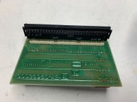
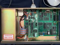
The Official Nabu PC Floppy Disk Controller thread
- Thread starter snuci
- Start date
snuci
Veteran Member
Klyball
Experienced Member
I will get it done as is then make that call if I can route with out to many changes@Klyball, are you duplicating @snuci’s board exactly and then adding the jumper wire and cutting the trace just like @snuci’s board? Or will you mod the traces to incorporate the fixes applied to @snuci’s board?
Klyball
Experienced Member
I will need you to at least verify some mystery traces@Klyball You tell me when you are finished and I can check it. I can also send it to you if that's the best method. You've put in a tremdous amount of work and it's much appreciated. I would just be a little cautious in case it gets lost in transit.
snuci
Veteran Member
More info from another Nabu PC project by DJ Sures. He's recreating the Nabu Network and it looks like there may be some Nabu disk access if you have the drive? I am very interested to try this.
misterblack
Experienced Member
Hi snuci, looking at your pics, your ribbon cable looks completely corroded. Typical for these terrible things -- they should not be blue/green under the white plastic, but gray/silver. It's copper under there and over time it goes bad, turning the blue/green as copper does.
If your controller isn't working anymore, it's highly likely the ribbon is bad. I did a repair on a TRS-80 Model 3 recently and the ribbon showed continuity, but it could not carry any current at all, so it was actually bad, so you cannot trust a DMM continuity test. You have to put load on each path.
If your controller isn't working anymore, it's highly likely the ribbon is bad. I did a repair on a TRS-80 Model 3 recently and the ribbon showed continuity, but it could not carry any current at all, so it was actually bad, so you cannot trust a DMM continuity test. You have to put load on each path.
snuci
Veteran Member
Thanks misterblack. Everytime I move the FDC controller boards I do a continuity test on all lines but I think I need to find something that will work. If you hve any suggestions, we will need something for the recreated cards as well so any thoughts for a 1x30 pin 2.54mm pitch cable would be welcome.
seat safety switch
Experienced Member
1x30 will be tricky - I see lots of 2x17 (obviously) and 2x15 IDC connectors. I’d be tempted just to do 2x17 so you can reuse straight PC floppy cables and not have to crimp a new one.
snuci
Veteran Member
You can use one side of a 2x30 IDC connector. A bit of a kludge but I think those are still available. I only have one old one in my parts bin but in the meantime, I have some of those arduino jumpers on order and a set of 30 female to female jumpers at 8" will do once I solder male pins to the FDC card.


Klyball
Experienced Member
I added some via so the wire is not needed, maybe go this route or not@Klyball, are you duplicating @snuci’s board exactly and then adding the jumper wire and cutting the trace just like @snuci’s board? Or will you mod the traces to incorporate the fixes applied to @snuci’s board?

snuci
Veteran Member
snuci
Veteran Member
I did replace my 30 pin flat ribbon cable but unfortuntely, same issue. I decided to install it on the underside instead of on top like the old cable. It tries to boot from floppy but motor continues to spin, light is on but nobody is home  I needed toreplace it anyway as it was starting to separate with all of the removing and installing I've been doing.


Last edited:
Klyball
Experienced Member
how's the condition of the 24 pin cable, have you beeped it out or looked at the connections,
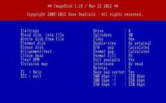
hows the clock signal , 2mhz for 8 inch drives 1mhz for 5.25 , i have also ran into problem making disks with IMD and having to force the timing to eg 250 or 300 depending in the need as it wasn't detecting automatically
hows the clock signal , 2mhz for 8 inch drives 1mhz for 5.25 , i have also ran into problem making disks with IMD and having to force the timing to eg 250 or 300 depending in the need as it wasn't detecting automatically

snuci
Veteran Member
I checked each of the 24 pins to confirm continuity on both sides when documenting the cable pinout. Pin 24 on the WD1797-02 is 1 Mhz.
I believe I made the disks correctly via the proper settings via ImageDisk and with the help of the "Bad Disk Image?" thread, I could verify them with 22Disk.
To be sure, I also made the disks with the actual Nabu disk drive. This is how I determined one of my drives is bad (B drive).
I appreciate the suggestions.
C128 Guy
Experienced Member
All this work is amazing guys. Still waiting for my ebay Nabu to ship, but very happy to join the party when it arrives!
1985MR2
New Member
@Klyball, I just saw Leo Binkowski’s YouTube video
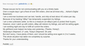
FYI, the eBay vendor is apparently snowed under with testing and shipping. Apparently he's working through the backlog.
- Alex
- Alex
Has anyone pulled the ROM's? Or done a disassembly? My NABU is still in its box… I'm waiting for the dust to settle. ;-)
But I've got guru Z80 disassembly skills (IDA Pro, Hopper, z80dasm, etc.) and would be willing to contribute if the ROM's are available.
But I've got guru Z80 disassembly skills (IDA Pro, Hopper, z80dasm, etc.) and would be willing to contribute if the ROM's are available.
C128 Guy
Experienced Member
snuci
Veteran Member
Has anyone pulled the ROM's? Or done a disassembly? My NABU is still in its box… I'm waiting for the dust to settle. ;-)
But I've got guru Z80 disassembly skills (IDA Pro, Hopper, z80dasm, etc.) and would be willing to contribute if the ROM's are available.
Take a look at what TheCodeMan has done here first: https://github.com/TheCodeman/Nabu_PC
The firmware for the Nabu PC is here: https://vintagecomputer.ca/files/Nabu/firmware/
Note that there are two versions. The eBay Nabu PCs use a 4k 2732 EPROM for the firmware. My floppy disk unit uses an 8K 2764 EPROM as there is more code for the floppy drive routines. Rev A is the normal one. Rev B is the floppy version. If you feel more needs to be done with Rev B, that would be great. I'd love to see more detail, if possible.

