• Please review our updated Terms and Rules here

Vectrex Repair (another no buzz 3GE version)

Hi demonlg.

You are saying that you are using a „multigame cartridge with a rom named TEST V4“ How do you know that this test cart rom is really running when you do all your measurements? Just wondering as you don’t see a clear picture on your screen and for my understanding on these kind of cartridges you will get a selection list first where you need to select that rom and then start it. Even when there is only one rom on that cartridge.

Only with that cross hatch test pattern (1. picture when starting the test cart) you will be able to get the right waveforms on the test points. I also prefer a native test cart because of that. I made a few carts by myself a while ago using a Vectrex blank board and a EPROM chip….

Still got one left. Send me a PN when I can help you with that. Otherwise good luck for you😊
 
But i'm confused for schematics, i have found this marked with 3GE schematics, but i don't find the LF353 and LF347 on my logic board!
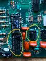
Look for IC303 and IC304 on the board. LF347 is equal as MC34004 and LF353 is equal MC34001. Or similar…
 

Attachments

  • IMG_0371.jpeg
    IMG_0371.jpeg
    3.2 MB · Views: 9
I can sit back now - I have trained an expert...

Even more importantly (after plenty of blood, sweat and tears) he has a working 3GE that can be used for comparison with voltage measurements and oscilloscope traces (providing you have the actual test cartridge running of course).

Well done @miata for stepping up to the plate!

Dave
😁 Haha. I don’t feel like an expert. Seriously. The Vectrex is still a kind of (beautiful) mystery to me! But good to have masters like you here, Dave 😊
 
Hi Miata and thanks for reply and support, and sorry for my english, i'm in Italy.

My external cartridge have a display for selecting game rom then select button reset the machine and rom is loaded, then i have a little sound sequence when start, but all my screens on the scope is tacked with built in mine storm game and not with test v4 loaded, i have missed to insert cartridge before measuring on pins!

I write you in pvt if i need thanks.

@Dave, thanks for explanation for chip part code, now is more clare all the schematics! Then i have now two new spare of MC34004, any new and used tested 4066, and in the next week arrive one MC34001 and two MC14052.

Now, i don't know if my signal are correct for your diagnose or i have missed all measurement. But now i try to desolder the 34004 and 4066 and try to replace both with new.

I'm sure thw 6809P and 6522 are good, and the MC14008P8, probably sound chip and rom because i have audio of the built in game.

Thanks for now.
 
Ok news, only for note, I have socketed all chip on logic board excluded the 74ls00 and 74ls32 and rom.

Then i have replaced:

PIA 6522
DAC MC1408P8
MC34004P (LF347)
CD4066BE

but nothing is changed, same issue with this new parts.

Then i have removed first IC304 (LF353N) and turned on the system, without IC304 display show more confused lines but centered on the screen, and with IC304 but without IC306 (second LF353N) the screen seems illuminated but out of border.

Then i have reinserted both LF353N and removed the MC14052B and turned on and i have five little lines at center of screen.

When the sound is out in speaker the lines, or dot, moving little bit on screen.

Ok tomorrow i have to retest with scope and with test v4 loaded.

But i don't have idea where is the problem, and method to check, i have ordered new x2 LF353 and x2 LF347.

I'm angry! :D
 
Last edited:
We have changed so much stuff now that we have to start again.

So, the first question is "how are we sure we are running the test cartridge code and not a 'game'"?

Ah, I re-read post #26 where you state that you were running mine storm. Ok, that's not helpful with the traces then...

Dave
 
Last edited:
Yes dave, tomorrow i repeat measurement with test rom loaded, but i don't have chance to change type of test because i'm not read nothing when press button to pass at next test.

Is it possible to attach little video on posts?
 
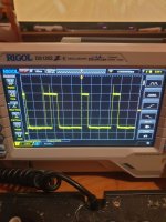
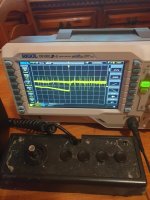
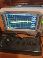
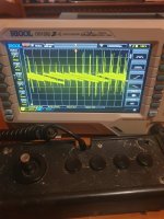
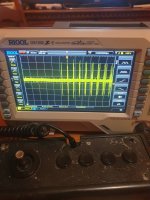
Again screens, now with test cart inserted and loaded, because i have a sound start of test rom.

Now 4066 signals:
172900 pin 5
172828 pin 4
172748 pin 3
172508 pin 13
172633 pin 1
172707 pin 2

Now next post with XYZ signals
 

Attachments

  • 20231029_172900.jpg
    20231029_172900.jpg
    1.1 MB · Views: 2
  • 20231029_172828.jpg
    20231029_172828.jpg
    1.1 MB · Views: 2
  • 20231029_172748.jpg
    20231029_172748.jpg
    1.1 MB · Views: 2
  • 20231029_172508.jpg
    20231029_172508.jpg
    1.1 MB · Views: 2
  • 20231029_172633.jpg
    20231029_172633.jpg
    1.1 MB · Views: 2
  • 20231029_172707.jpg
    20231029_172707.jpg
    1.1 MB · Views: 3
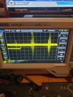
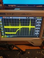
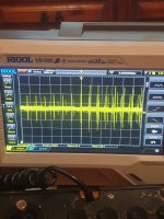
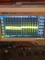
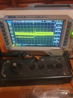
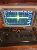
Now XYZ with test cart inserted:

173618 X
173701 Y
173736 Z
 

Attachments

  • 20231029_173736.jpg
    20231029_173736.jpg
    1.1 MB · Views: 2
  • 20231029_173701.jpg
    20231029_173701.jpg
    1.1 MB · Views: 2
  • 20231029_173618.jpg
    20231029_173618.jpg
    969.5 KB · Views: 2
Z is fine. X and Y are clearly rubbish...

Let me have a look at the other signals you posted. You changed the 4066 didn't you?

Dave
 
The /ZERO switching signal (pin 13) is nice and clean. The /RAMP signal (pin 5) not so.

These come from the 6522 and the /RAMP signal could look like that (depending upon how we trigger the oscilloscope).

The signals going into the 4066 switches are rubbish also...

Can you measure IC302 pin 12 (on the 4052) and IC302 pin 13 (also on the 4052) next please.

See what the DAC and analogue multiplexer/switch are up to...

Dave
 
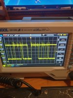
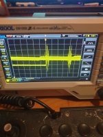
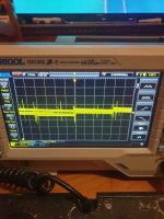
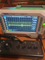
This the pins 12 and 13 of 4052:

183138 pin 12
183303 pin 13
 

Attachments

  • 20231029_183138.jpg
    20231029_183138.jpg
    1.1 MB · Views: 2
  • 20231029_183303.jpg
    20231029_183303.jpg
    966.6 KB · Views: 2
This is not good either...

Question, have you tried slowing down the oscilloscope timebase? I am just wondering whether you are actually missing the signals and the oscilloscope is presenting signal noise to us?

Dave
 
My mistake, sorry i have wrong counted pins, this are correct pin, last post are wrong pins 13 and 14...

Now i have tested 12 and 13 with auto sens of scope for first two photo and then i have moved time div from 50us to 5us for both second two photo:

191954 pin 12 50us 200mV
192045 pin 13 50us 200mV
192242 pin 12 5us 200mV
192257 pin 13 5us 200mV
 

Attachments

  • 20231029_191954.jpg
    20231029_191954.jpg
    1.1 MB · Views: 1
  • 20231029_192046.jpg
    20231029_192046.jpg
    1.1 MB · Views: 1
  • 20231029_192242.jpg
    20231029_192242.jpg
    1 MB · Views: 0
  • 20231029_192257.jpg
    20231029_192257.jpg
    1 MB · Views: 1
Oh! i have found a problem! Rollbacked to check power supply line, i need 3 voltage for logic board to working, +5v -5v and -13v.

Now, and only now, i have noted a loss -5v when logic board power connector is inserted in it, but is ok if i disconnect power connector from the board!

when connected the -5v rail drop down to -0,66v !

+5v and -13v rails are ok
 
Last edited:
So,

You either have a short circuit on one of the components connected to the -5V rail (only the analogue components are connected), or you have messed the desoldering/soldering up and shorted -5V to 0V/GND.

Dave
 
Ok, but the problem is the same before desoldering, but now I check for short, i have checked on schematics -5v going to pin 4 of 353 and pin 7 of 4066 for now, if i temove both 353 and 4066 the short is present.

I check for other destination, i update if i found the short.
 
Back
Top