• Please review our updated Terms and Rules here

Vectrex Repair (another no buzz 3GE version)

I confirm the loss of -5v when connected but is not a short, or a full short, if i measure gnd to -5v for continuity i don't have short.

I have removed all chip supplied with -5v, 4052 pin 7, LF353's pins 4, LF347 pin 11, and 4066 pin 7, but if i power up system i have same drop on -5v rail.

I have checked all 0.1uF caps influenced from this rail, from gnd and -5v, but nothing, the 100uF16v replaced is in correct way position.

Nore: with power connector disconnected from logic board i have:

-6,2 v on -5 rail *
4,98v on 5v rail
-12,98v on -13 rail

* This is high for me, is possible a fault on 7905 regulator circuit?
 
Last edited:
Indeed. This is far off. Should be in a range of -4,8V to -5,2V

Did you measure this value right at the 7905, at the output pin? What’s the voltage at the input pin (the middle one)?
 
Agreed. Check the input, ground and output pins of the 7905 -5V regulator - all pins with reference to 0V/GND.

I know it sounds strange to check ground and ground - but if the ground pin of the regulator is not making good contact this can cause problems.

Take the readings both with the cable connected to the logic board AND without the cable connected.

If the 7905 regulator has a metal tab, make sure this is not shorting out to anything. The metal tab is usually connected to one of the three regulator pins.

Dave
 
Ok Dave and Miata, I'll check it tonight, I measured with a multimeter straight from the connector, black on the ground wire and red on the -5V wire, unplugged from logic board, and if plugged i have +0.65v and not -0.65v wtited in previus post.

I haven't checked the 7905's metal plate but it has a 7905 mica insulator and heat sink
 
Last edited:
Ok when connector is connected to logic board and black wire of multimeter on GND i have on 7905:

pin1 input 0.0 volt
pin2 center -10.3v
pin3 output 0.66 volt

with connector disconnected from logic board

pin1 input 0.0 volt
pin2 center -13.7 volt
pin3 output -6.4 volt


Metal tabs of 7905 don't have short with other.
 
I think you will find (from the 7905 datasheet) that pin 1 is ground, pin 2 is the input and pin 3 is the output.

Either you still have a short circuit somewhere after the voltage regulator, or the voltage regulator is duff.

-6.4 Volts is too high (low?) for a voltage regulator of this type.

Do you have a low power 6V bulb. If so (with the logic board disconnected from the power supply board) can you light the bulb if it is placed between ground and the -5V regulator output?

That will test the voltage regulator out itself.

If the voltage collapses, the regulator is toast.

Dave
 
yes im sorry for wrong pin label all right.

I have a short on the analog board for you?

I try to replace 7905, and check other components in the area.

Probably i don't have a bulb, but i have a big ceramic resistor 10w can i use it ?
 
i have tested now with resistor 10ohm 17w connected on the power connector and i have 0 volt on -5 rail output.
 
5V / 10 Ohms = 0.5A.

Can you just check the input voltage to the 7905 voltage regulator with your resistor connected to the output of the voltage regulator - just to make sure that the input voltage is still there and hasn't collapsed.

Dave
 
Ah, no Volts in to the voltage regulator = no Volts out of the voltage regulator.

You need to follow the voltage back, remembering that on the secondary of the transformer winding it is AC not DC.

Also, you haven't got a faulty switch have you? Miata knows all about those!

Dave
 
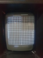
ok Dave i jave desoldered 7905 and it is fault, i have changed and now:

I have to make a regulations on trimmers?
 

Attachments

  • Screenshot_20231030-220645_Telegram.jpg
    Screenshot_20231030-220645_Telegram.jpg
    604.9 KB · Views: 2
  • Screenshot_20231030-220708_Telegram.jpg
    Screenshot_20231030-220708_Telegram.jpg
    521.8 KB · Views: 2
Right, so use the Vectrex test cartridge and the adjustment procedure now...

So the fault was a straightforward 7905 regulator fault in the end?

Good work in the end!

Dave
 
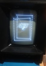
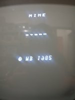
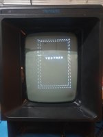
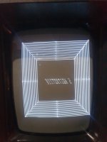
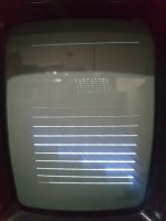
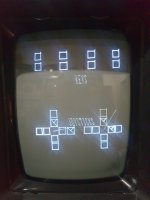
Yes probably only the 7905 for video iasue, then i have replaced again original 6522 because not change with regulations, but any characters of text are writed in wrong mode, specular!

You see in this photo the scrolling text with wrong rotation of letters.
 

Attachments

  • Screenshot_20231030-223826_Telegram.jpg
    Screenshot_20231030-223826_Telegram.jpg
    656.5 KB · Views: 7
  • 20231030_224822.jpg
    20231030_224822.jpg
    501.3 KB · Views: 7
  • 20231030_224815.jpg
    20231030_224815.jpg
    595.6 KB · Views: 7
Just for added info, now the -5 volt rail have -4,95 volt without connector inserted to logic board, and -4,92 connected.
 
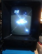
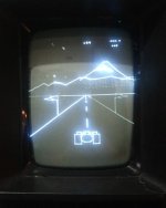
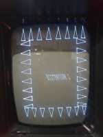
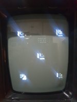
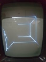
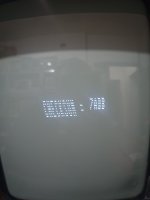
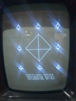
The screens of test cart, i have just moved trimmer and now text seems writed in correct way but is not perfect.

Then the controller test, button all ok direction up ok down ok right move on joy 2 but im on joy1 left not working.
 

Attachments

  • 20231030_233836.jpg
    20231030_233836.jpg
    1.5 MB · Views: 5
  • 20231030_233830.jpg
    20231030_233830.jpg
    773 KB · Views: 4
  • 20231030_233822.jpg
    20231030_233822.jpg
    645.5 KB · Views: 5
  • 20231030_233817.jpg
    20231030_233817.jpg
    790.1 KB · Views: 5
  • 20231030_233805.jpg
    20231030_233805.jpg
    818.8 KB · Views: 6
  • 20231030_233753.jpg
    20231030_233753.jpg
    476.8 KB · Views: 5
  • 20231030_233744.jpg
    20231030_233744.jpg
    857.5 KB · Views: 5
  • 20231030_232236.jpg
    20231030_232236.jpg
    1 MB · Views: 6
  • 20231030_233843.jpg
    20231030_233843.jpg
    990.1 KB · Views: 5
Getting better.

All of the potentiometers (two from each controller) go into 4 pins of the 4052 IC302.

Measure the potentiometer voltages there as you move the joysticks around.

What, if any, are the differences between your test cartridge images and those in the documentation?

I do see some differences. These could be either latent defects or further adjustments required.

Dave
 
Back
Top