• Please review our updated Terms and Rules here

Vectrex Repair (another no buzz 3GE version)

demonlg

Veteran Member
Joined
May 22, 2016
Messages
521
Location
Italy
Hi to all,

i have readed all other post of MIATA user and the last is the same of my board.
I have a strange issue, similar to one of Vectrex of miata but with other type of board. The attached image is the problem, i have the vector concentrated on center/bottom left of screen but confused or mixed!
The system boot up and i have sound of builtin game milestorm.
I have recapped both boards and i have exchanged the 6522 with other 3 tested on my Commodore VIC20, i have washed board and socketed CPU and replaced oxided socket of 6522 and audio chip, but the problem is the same, then i have noted a socket on MC1408P8 chip and replaced it too, but nothing. Game start, audio is ok, reset is ok but vector same of the attached image.

I have ordered one MC1408P8, one MC14052B, two MC34001P and one MC34004P, but arrive in the next week probably.

I have a multigame cartridge with a rom named TEST V4, have the scope and all instrument.

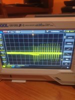
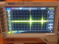
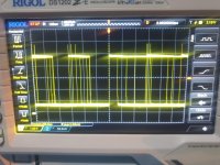
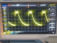
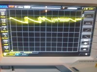
Yesterday i have checked the X,Y,Z signal but i don't know if are correct or not.
Then i have checked voltage, i have +5v -5v and -13v con the connector from analog board power supply, and the -13v are present in a pin 3 of MC1408P8 DAC chip.

Can any one help me? Dave :D ? What other check i have to try?

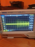
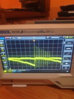
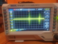
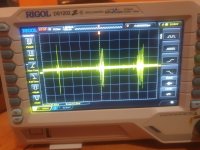
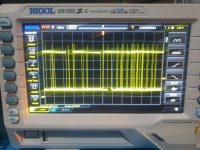
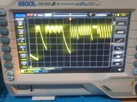
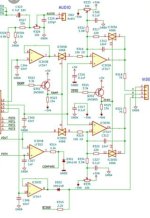
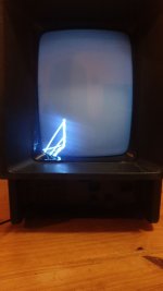
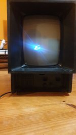
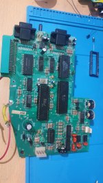
In order, first photo is during built in game demo, second photo is at first power up with sound of VECTREX WELCOME SCREEN, and third photo is my logic board.

Thanks

Emanuele
 

Attachments

  • photo_5883990494579638079_y.jpeg
    photo_5883990494579638079_y.jpeg
    75.6 KB · Views: 9
  • photo_5883990494579638078_y.jpeg
    photo_5883990494579638078_y.jpeg
    103.3 KB · Views: 9
  • photo_5883990494579637843_y.jpeg
    photo_5883990494579637843_y.jpeg
    168.2 KB · Views: 9
Last edited:
So, as I mentioned in my DM, you ideally need to purchase a test cartridge.

Here is one available from ePay in the UK: 154777521811.

The Vectrex service manual contains the documentation and the various oscilloscope traces that should be present at various points throughout the electronics. @miata has also done an excellent job of documenting other oscilloscope waveforms that were missing from the service manual.

Yes, it is a little sick isn't it...

Dave
 
I have only this waveform on one of founded service manual. I try to check if i have same waveform on the XYZ connector, then i don't find IC 401 or 501 on my board.

1698330462268.png
 
I misunderstood what you said about your test ROM. That's fine then if you are using that...

IC401 and IC501 are on the power board - not the logic board.

IC501 is the 555 timer that produces the high voltages for the CRT. Because you see an image, it is unlikely to be IC 501.

IC401 is an LM379 that drives the horizontal and vertical scan coils (X and Y deflection). You won't 'see' this IC on the power board because it 'hides' under the big heatsink!

You can still measure the signals by chasing them back to R402 and R409 (where pins 7 and 8 are driven from).

Dave
 
Dave i have to measure it signals at the red point of this schematics right?

1698339364878.png
 
I will check all D405 to D412 1n4148 also .... The coil yoke seems to be fine.
 
Yes, but I would check miata's oscilloscope traces for your reference waveforms rather than the poor ones in the manual.

Miata's traces include more points than the manual, and these can be used to checkout the functionality of IC401 if the inputs to it are OK.

Dave
 
I try to check input now, but i need to save all single image of Miata to check all other signal
 
This is signal on xyz connector with test cartridge inserted and after start sound.
first photo 233942 is x, second 234020 is y and third 234113 is z

The signals is not the same of Miata, then i.have checked signal on input of lm379 and i have two similar signal but not same of Miata too.

I don't say if scope is setted correctly.

I have the square on the 555 output same of schematics.
 

Attachments

  • 20231026_234113.jpg
    20231026_234113.jpg
    1 MB · Views: 2
  • 20231026_234020.jpg
    20231026_234020.jpg
    1 MB · Views: 2
  • 20231026_233942.jpg
    20231026_233942.jpg
    1.1 MB · Views: 2
And now lm379 001555 pin 7, 001633 pin 8, 001705 pin 6 and 001729 pin 9.
 

Attachments

  • 20231027_001729.jpg
    20231027_001729.jpg
    2 MB · Views: 1
  • 20231027_001705.jpg
    20231027_001705.jpg
    2.4 MB · Views: 1
  • 20231027_001632.jpg
    20231027_001632.jpg
    1.9 MB · Views: 1
  • 20231027_001555.jpg
    20231027_001555.jpg
    1.9 MB · Views: 1
Other test, i have changed 6522 with another one sure working and the MC1408P8 but nothing changed, sound ok, video same issue.

Today arrived the MC34004P and i'll try to replace this night.

I have buyed LM379S in UK from ebay but i don't know when arrive!
 
You do not have a correct X and Y signal - so the problem is most likely to be on the logic board as opposed to the power board.

There are quite a few possible candidates for being faulty (as the analogue circuitry is fairy convoluted).

I would have scoped around the X-AXIS signals first (e.g. 4066 pins 3, 4 and 5 and 4066 pins 1, 2 and 13) before replacing anything, but it seems like you prefer to replace chips...

Dave
 
Ok signals on 4066:

photo 5422 pin 3
photo 5548 pin 4
photo 5727 pin 5
photo 5858 pin 1
photo 10112 pin 2
photo 10325 pin 13

I think so wrong pins 3 and 4?

And from the schematics in next post it is Y signals or is X signals?

Emanuel
 

Attachments

  • 20231028_010325.jpg
    20231028_010325.jpg
    2.1 MB · Views: 2
  • 20231028_010112.jpg
    20231028_010112.jpg
    2.6 MB · Views: 2
  • 20231028_005858.jpg
    20231028_005858.jpg
    2.1 MB · Views: 0
  • 20231028_005727.jpg
    20231028_005727.jpg
    2.1 MB · Views: 1
  • 20231028_005548.jpg
    20231028_005548.jpg
    2 MB · Views: 1
  • 20231028_005422.jpg
    20231028_005422.jpg
    2 MB · Views: 3
Last edited:
But i'm confused for schematics, i have found this marked with 3GE schematics, but i don't find the LF353 and LF347 on my logic board!
 

Attachments

  • Screenshot_20231028-012057_Gallery.jpg
    Screenshot_20231028-012057_Gallery.jpg
    544.8 KB · Views: 5
  • IMG_20231028_012438_277.jpg
    IMG_20231028_012438_277.jpg
    208.8 KB · Views: 5
Back
Top