• Please review our updated Terms and Rules here

Wang Series 700B Advanced Programming Calculator Refurb.

And just to confirm at least 1 thing, running the machine with just the other card in the X slot (with the weird diode) results in a completly undstable machine around that 180 V AC mark... and a shimmering display above that 180 V AC mark with a rapidly heating diode. So that is at least part of the problem... I wonder if something in the voltage regulation is now also unhappy.

If it's zeners that are going out of spec and thus draw more power then needed, why does the machine run on a lower voltage? Are they then more in line with what would be expected?
If it doesn't hurt anything else in there I would happily keep it at around 180 V AC and use it like that. I guess the cassette mech would not work well, mainly the motor, but I mostly use the tape adapter and laptop for loading and saving and that seemed to work fine at a lower voltage.
 
So, my limited knowledge of zeners is that typically they are wired reverse-biased with a series resistor from the input (higher) voltage. That resistor is chosen to maintain a "reasonable" reverse current through the zener throughout the expected input voltage range. But a small increase in input voltage can produce a huge increase in diode (reverse) current, as you are operating right at the "knee" of the V-I curve. So, typical failure mode is that the input voltage goes too high causing a massive current to flow and melting down the diode (after which the diode does not operate correctly ever again). So, all a very fragile balance to be maintained.

Regarding you seeing the +5V go down at the L505 card, if you're measuring at the actual connector pin (or card edge finger) then it seems likely that the wire connecting that pin to the +5V common is "high resistance". The more current drawn by the card, the lower the +5V will go. So, that L505 card might be drawing too much current, perhaps due to that diode, but the reason you don't see lower +5V on other cards is that it's just the wire/connection to that one card (or section of the card cage) that is bad. If I recall correctly, the 700s use a connection scheme similar to wire-wrap, except that there is some sort of crimp-on thing to secure the connection.

Still, it is even possible that there is nothing wrong with the wire/connection but it is simply the amount of current being drawn is such that any wire would drop the voltage. But I'd have to think that would be "sparks and flames" sort of thing... but who knows.
 
So, my limited knowledge of zeners is that typically they are wired reverse-biased with a series resistor from the input (higher) voltage. That resistor is chosen to maintain a "reasonable" reverse current through the zener throughout the expected input voltage range. But a small increase in input voltage can produce a huge increase in diode (reverse) current, as you are operating right at the "knee" of the V-I curve. So, typical failure mode is that the input voltage goes too high causing a massive current to flow and melting down the diode (after which the diode does not operate correctly ever again). So, all a very fragile balance to be maintained.
I think I see how that should work. That might mean that if I run the machine at a lower supply voltage it might be better for the zeners anyway?

I'm going to see if I can harvest those 2 disk caps from an old computer PSU and see if combining them bring them close to that 4700 that is on the other card.
If both displays can be used again, I can then try and figure out if somethings up with the regulator boards.
 
OH, and if your theory about the 0V line being the culprit is correct, you should be able to measure a small voltage between the 0V on this card and the 0V someplace "more healthy" on the chassis. Otherwise, we need to address why the diode on the 250V circuit is affecting the +5V. One thing I now notice is that this suspect component is effective in parallel with the series-pair of D2s (zeners) on the far left of that circuit. That could screw up a lot of things, if it is supposed to be a capacitor.
 
OH, and if your theory about the 0V line being the culprit is correct, you should be able to measure a small voltage between the 0V on this card and the 0V someplace "more healthy" on the chassis. Otherwise, we need to address why the diode on the 250V circuit is affecting the +5V. One thing I now notice is that this suspect component is effective in parallel with the series-pair of D2s (zeners) on the far left of that circuit. That could screw up a lot of things, if it is supposed to be a capacitor.
Oh, you're right!
So, the way I was thinking about this going wrong is that the diode was installed in such a way that it is blocking the + 250 V from shorting to the 0 V. So as long as that diode is doing it's normal job nothing would really happen, you're missing a small filter cap on the +250 but that would be all. And since that cap was only added in a revision, to a point everything should work "fine" without it.

But now the diode is breaking down and conducting in the wrong direction and thus allowing the 250 V to short to the 0 V and heating it up. I don't think it's fully shorted yet though (mainly because it still a diode according to my multimeter).
I was able to get the machine on with the bad card installed, but as soon as any key got pressed it would break and the diode heats up. At lower supply voltages I could press keys but only the verify program key worked most of the time... the rest didn't do what it should (that's why I thought the Vcc on the TTL logic in the machine was biased wrong as it's doing all sorts of random things).
 
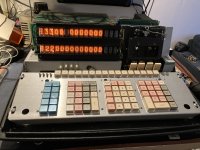
Alright, while that didn't fix everything, it did fix the machine not working properly at all. I now have 2 working displays at a supply voltage of around 185 V AC. 1 tube isn't working... but that 1 has been on it's way out for a while, at least swapping the board around kind of confirmes for me that the tube is going bad and it's not an issue with the Y card.

Mostly-fixed.jpg

Oddly enough, behaviour at a higher supply voltage has not changed, display goes shimmery or it seems to run amock, somewhat dependend on how high the supply voltage is (the higher the less functional). But I'm not seeing any odd hot components on the X and Y cards so that seems to be at least fixed.
 
I had some time this afternoon and tried to get a better look (both visually and thermaly) of the PSU section that is hiding under the main chassis. This is pretty hard to get to, I ended up not removing the chassis 2 years ago because, well, it wasn't really worth the risk.

When peeking through a hole in the chassis underneath the transformer with the FLIR camera, I noticed a pretty big hot spot. Getting the FLIR to focus on it is pretty difficult through such an opening (and I thought it would just be another power resistor) but it turns out it's a pair of diodes that are getting pretty near to 100 C. Looking a bit more with a small light I noticed another pair next to it, these were far from warm.

PSU-diodes.jpg

I believe these diodes are the 1N4719 diodes before the 5 V and 12 V regulation circuits.

Whenever I have some time to do more indepth work on it I want to solder some test wires to the plus and minus low voltage rails and measure them. There is also a power failure circuit that takes a number of voltages through a comparitor/opamp or something like that and generates a couple of signals that go into the machine.

I did measure the +250 VDC and, while running on the lower 185 V AC from the variac, it sits around the 205 VDC mark, which is fine.
I did notice that on this lower voltage here is another nixie that doesn't work well, but it's in the exponent area of the Y display. So the Y display is down 2 tubes at the lower mains voltage... I might need to find some replacements...
 
That certainly seems like too hot, and that might explain the odd behavior of the +5V rail. Of course, it might just be a symptom of something drawing too much current on +5V, too. It is difficult working on these, at least for those of us that never saw the Wang service documents explaining how to do that. It would be interesting to see old photos of the service benches used to fix these things.
 
Honestly, I'm wondering if the "weird" behaviour on the +5 is down to measurement errors on my side. I may have had a weird value at some point. But once the machine is opperating (no matter where the mains input voltage sit between 185 VAC and 230 VAC) the +5 is a solid 4,85V. Now, this might still be a little low (I'd rather have it at 5 and a bit), but it's not moving away from that 4,85V. (except on the display board, but there was a diode between the +5 and the place where I measured, so the 4,2 ish is not bad perse).

The hot transistors can be either be for the 5 or 12 volt regulation... one of the main things I would suspect here is actually the 2 big caps after the diodes. These are 55 years old now (as are all caps in this machine btw except for the one I just installed on the display driver and 1 on the negative voltage regulator board that had some crusties on it 2 year ago).

This is why I first want to meassure all 4 low voltages to see if one goes out of spec at higher mains input voltage. Because the +5 seems pretty stable, I'm wondering if the +12, -12 or -5 do something funny to throw of something inside. Going through the schematics to see where they go the 12V is needed for the core memory drivers... so I could see functions of the machine breaking down as memory operations go unstable.

And then there is the Power Failure Protection... I'm not sure what it does exactly, but the 2 outputs from it go to multiple boards. And it has inputs to a opamp/comparitor several voltages.

I hope to get these 4 voltages on the scope over the weekend to see how they behave.
 
...
And then there is the Power Failure Protection... I'm not sure what it does exactly, but the 2 outputs from it go to multiple boards. And it has inputs to a opamp/comparitor several voltages.
...
At one point I had convinced myself that that was to provide a consistent power-on state (not always succeeding). I know the Wang 600 I used in high school would power-on "clean" most of the time, but not always (landing in an error state, as if you entered too many digits into the display). We just got in the habit of always pressing PRIME after turning on the power, whether it (appeared to) need it or not. But, I have not reviewed that circuitry recently. The main goal (if I'm right) would have been to ensure the power on triggered the same thing as pressing PRIME (clean jump to location 000 in the microcode ROM). The Wang 600 had static RAM, though, and so it might have been worse for core memory where the contents might resemble the last thing ran before power off.
 
At one point I had convinced myself that that was to provide a consistent power-on state (not always succeeding). I know the Wang 600 I used in high school would power-on "clean" most of the time, but not always (landing in an error state, as if you entered too many digits into the display). We just got in the habit of always pressing PRIME after turning on the power, whether it (appeared to) need it or not. But, I have not reviewed that circuitry recently. The main goal (if I'm right) would have been to ensure the power on triggered the same thing as pressing PRIME (clean jump to location 000 in the microcode ROM). The Wang 600 had static RAM, though, and so it might have been worse for core memory where the contents might resemble the last thing ran before power off.
Hmm, interesting... the thing is, I don't think I have ever had this thing power up in an error state for as long as I've had it. Well, until last weekend that is...
Maybe this is because I always use the Variac to slowly bring up the power supply (first time after not using it for a while I take a pretty good long time to power it up and then let it sit for a bit before actually doing things). I never first bring the voltage up to a certain point and then click the machine on.

It is true though that the core memory retains whatever was in there. When I first started using the programming functions after the repairs 2 years ago, there were still bits of programs in memory. Including the little example program from the user manual for Pythagoras Theorem. But also a lot of old parts of the programming that it ran back in the day when it was used in a water treatment plant.
The guy that sold the machine to me had only turned it on to see if it would light up, he demonstrated that much to me when I went to pick it up. He had no idea how even to do calculation on it, he just found the thing somewhere in his dads attic after his dad passed away among a collection of vacuumtube repair hobby stuff. His dad was one of the engineers that originally worked with this machine at the water treatment plant. So that Pytagoras Theorem program in memory was typed into it at some point in the past, likely decades before I obtained it.
I have a bunch of paperwork from the late 70's that was sent to the original owner from a Wang dealership with info on various calculators and peripherals... nothing unique though, I believe it's all on archived already.

This core memory seems to hold on to it's contents for ages, or so it seems.
I have turned the machine off with programs still in memory and it would happily run them from memory again after months of inactivity.
 
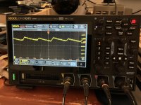
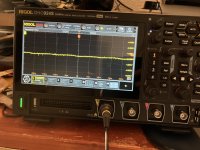
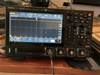
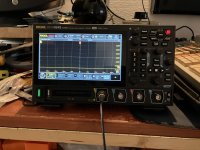
So, I've had the voltage regulation on the scope. And while 3 of the voltages look fine (although they are all a bit on the low side) the +5 V has a significant ripple on it. They were measured directly from board 336, where the negative voltages are generated and the Power failure protection is.
This is the + 5V

5volts-scope.jpg

The - 5V

-5volts-scope.jpg

The +12 V

12volts-scope.jpg

And -12 V

-12volts-scope.jpg

Apart from the +5 (in my opinion) the other voltage look pretty clean. I don't really understand why this makes the machine unstable above that 185 VAC from the mains though.

Increasing the mains input up for here to around 200 to 210 VAC actually cleans all the voltages up. They all go to pretty much perfect in both waveform and value... but at that point I can no longer operate the machine. It'll either do random stuff or the screen goes blank with just a few digits in X lightly shimmering.


So... when the regulated voltages are not quite correct and not really clean... it works "fine"... but when everything gets regulated to "perfection, it breaks down...

QUICK edit...

All but the -12 VDC go perfect... that one kind of sticks at -11,4 V when I turn the voltage up.
 
Last edited:
So, one of the things I hadn't tried yet was to program the machine in learn mode at 185 VAC input voltage... and I can't. Whenever I press a key to program into any step the display goes blank except for the most right nixie, which will show a very bright "0". Also the Prog Error light comes on. Sometimes the code for the key pressed does hold though, but sometimes the code goes to "00 00".

Oddly enough, it had no trouble loading from the tape drive earlier under the same conditions.
 
I just restarted the 700 and programming the memory in "Learn" mode works now, as does loading programs through the tape deck... so whatever is affecting it seems to get worse over a certain up time.
 
Sounds like another use for your FLIR, comparing images when it's working to when it's not. Of course, lots of things will be warming up over that period, but perhaps something will stand out. Resistors become higher resistance when hot, but silicon becomes lower. The exact effects will vary with the components location in circuitry (might raise or lower voltage, for instance). Note that even a degraded connection (crimp-wrapped bus under chassis) can be affected by heat, usually in that case raising the resistance (although expanding metal might actually improve a connection - probably not in this case). You might be able to chill a suspect component/connection and see if things start working again.

Andrew (https://dopecc.net/calculators/wang/600/) had a Wang 600 with severe damage to many of the ICs. The behavior in those cases was not always obvious. In that case, Andrew was using a wire-ROM replacement with [E]EPROMs that we could program with diagnostic microcode to help isolate what things were not working, narrowing down the possible components. What I mean is that there could be some IC that misbehaving (after warm up). Whether that's easier to fix than a discrete component all depends on availability of replacements - there are plenty of each type that are no longer available. But, if you're seeing critically low +5V in some places, that probably needs to be tracked down first. And monitoring voltages between cold and hot conditions might help, too.
 
Sounds like another use for your FLIR, comparing images when it's working to when it's not. Of course, lots of things will be warming up over that period, but perhaps something will stand out.
Yeah, I have been monitoring various things using the FLIR while the machine is working. Nothing really stands out currently (apart from the 2 rectifier diodes underneath the chassis. But they stay consistant in their temperature over time and input voltage). Most components (including resistors and so forth) don't really go very hot. I also can't really see any heat coming through the card edge connectors that would make me suspect a bad contact down there.

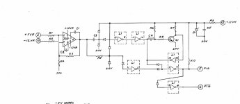
But I was wondering about something.

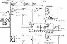
Power-Failure-Protection.jpg

After yesterdays tests, it seemed that with increasing the mains input voltage, everything slowly went up to their nominal DC voltage. So, at around 220 VAC mains input. the +5 was pretty much +5, the -5 was pretty much -5, and the +12 was pretty solidly +12.
But the -12 never really got above 11,2 or 11,3 ish. And the bigger the gap between the -12 and the rest, the less functional the machine was. And I also think the -12 got slightly worse over time while testing yesterday (although I think I would have to repeat the experiment to really draw that conclusion.
But in the Power Failure thingy, the -12 is "mixed" with the +5 at pin 7 of that 709. I wonder if the input at that pin might be out of spec if the -12 goes to low in comparison to the +5... thus messing with those signals at pins 5 and 6 (the PIG signals) that go into the machine.

I can't really reach the pin on that 709, but I can reach the pins of L1. I also want to solder some wires to the outputs on pins 5 and 6 of the board to monitor the PIGs while I mess with the input voltage.

But, if you're seeing critically low +5V in some places, that probably needs to be tracked down first. And monitoring voltages between cold and hot conditions might help, too.
From what I've seen yesterday... the +5V coming out of the regulator seems to be fine. Currently, it seems now that the "nicer" the +5V looks the worse the machine behaves :)
 
Did you ever figure out what the -12V is used for? I'm not immediately finding anything in the schematics. I think on the 600s that is used for the MOS RAM, and the ROMs in later versions. So there I could see a flaky -12V causing all sorts of problems (although those semiconductors aren't real picky and tolerate a wide range on -12V as I recall). I have not looking into PIG nor analyzed that circuit. If the only purpose of the -12V is to balance out the supply voltage on the 709 (compared to +12V), then if the absolute values for -12V and +12V differed too much I could see that comparitor no longer functioning correctly. But it's going to take a lot more blows to my head before I understand that PIG circuitry.
 
Did you ever figure out what the -12V is used for? I'm not immediately finding anything in the schematics. I think on the 600s that is used for the MOS RAM, and the ROMs in later versions. So there I could see a flaky -12V causing all sorts of problems (although those semiconductors aren't real picky and tolerate a wide range on -12V as I recall). I have not looking into PIG nor analyzed that circuit. If the only purpose of the -12V is to balance out the supply voltage on the 709 (compared to +12V), then if the absolute values for -12V and +12V differed too much I could see that comparitor no longer functioning correctly. But it's going to take a lot more blows to my head before I understand that PIG circuitry.
Yeah, that PIG thing is a... a bit of pig to figure out. But those signals do turn up at a couple of cards, so they are at least somewhat important.

I don't have much time this and next week to really dive into schematics and play around with the 700. I have quite a large job the coming weeks. But I do have a longer weekend coming up after that, so that would give me some time to sit down and really look for things again.
I will try to have a browse and see if the -12 serves any other critical rolls anywhere, I can't imagine it's only used to make that comparitor do something.
 
I did take a quick look through the schematics and the only other place I can see the -12 V being used is in another 709 that is used for the tapedrive. I couldn't quickly spot another mention of the -12 V.

The PIG signal goes to Board 5921: the Sense Amp. Osc. Core Bit Drive. Where it is connected to 2 NAND gates that also connect to the CLOCK. Not sure what it's doing there, but that sounds like an important one to have working correctly.

And the \PIG (i guess, it's inverted counterpart) goes to Board 5928, which is a "Buffer Board". On which it is involved in another messy circuit.
 
Back
Top