• Please review our updated Terms and Rules here

Wang Series 700B Advanced Programming Calculator Refurb.

Aha! Thanks for the pointers to PCBs receiving PIG... My eyes were not able to find those. So, the PIG going to 5921 is actually enabling the main system clock (co-resident on the board with the core memory sense/drive stuff). So, that should prevent the microcode from being executed until reaching PIG. Of course, a flaky/fluctuating PIG would certainly destabilize things. The /PIG on 5928 looks to me to be a suppression signal for read/write (RDWT) and also a de-assert for GPRM (PRIME) which should effectively work the way RESET does on most modern computers - holds things in reset until the power stabilizes, then releases the processor and ensures it starts in a known state.

The whole RDWT thing is a little fuzzy, but I seem to recall that signal being an enable rather than an actual read-write pulse.

Are you able to put a 'scope on PIG and watch it?
 
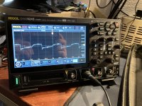
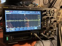
I did an attempt at getting the signals on the scope (I'm very much a novice when it comes to this scope). The signals are noisy, but I think they are pretty much where they should be. As with all voltages, the high signal goes up as the voltage increases. If I understand the schematic correctly, PIG should be low, so that each time the CLOCK goes low the output on the NAND gate is high clocking the flip-flops on board 5921.

The other one, /PIG... is going to be the inverse of that because there is an inverter between the 2 so should be high, not sure how that relates to the circuit behind it, I have not really looked into that.

Anyway, PIG is indeed low and stays low even when the machine becomes unstable and inoperable. It is also always this noisy.

PIG.jpg

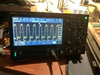
The other one is high, and stays high. But the peek does creep closer and closer to 5 Volts as the supply voltage increases. The waveform stays the same.

PIG-.jpg

Both signals stay roughly the same regardless of the state of the machine.

Could the ripple on either of those signals be enough to throw off the stuff that it relates to?
 
Just to be sure, I put a probe on the crystal. My thought was, maybe the crystal became marginal and it only worked at slightler lower voltage (I guess it would run of the +5).
But it seems to work fine. It runs at 8 MHz which is what the schematic says it should be. This is measured directly from a leg on the cristal.

Crystal-scope.jpg

Getting a scope from the chip that makes a proper square wave from this is a bit more tricky.
 
It might be good to look at the system clock outputs, like P0,P1,...P10, to make certain they are behaving correctly. Of course, if PIG was glitching and only causing the occasional drop-out of clock, that would be hard to detect on a 'scope.

I guess another possibility is that the wire-weave ROM shows unreliable behavior. I know from working with Andrew that those circuits can age and fall out of spec. The schematics hint at the need for some sort of tuning, as there are capacitors that are listed in the notes as being chosen to meet timing or added to noisy bits.
 
It might be good to look at the system clock outputs, like P0,P1,...P10, to make certain they are behaving correctly. Of course, if PIG was glitching and only causing the occasional drop-out of clock, that would be hard to detect on a 'scope.
To get to those, it would be good to make some riser boards. The crystal was just about reachable with the probe... well, I guess I could use the wires that came with the logic analyzer probe (with the little hooks). But at that point the signal will become noisy just because of the long leads.
If it's only the occasional glitch I can see it being hard to get on the scope indeed...

I guess another possibility is that the wire-weave ROM shows unreliable behavior. I know from working with Andrew that those circuits can age and fall out of spec. The schematics hint at the need for some sort of tuning, as there are capacitors that are listed in the notes as being chosen to meet timing or added to noisy bits.
Would that include the actual voltage that it gets? So, let's say some component in there drifted far enough that it's no longer happy with +5 or +12 exactly, but when it gets +4,5 and/or +11,2 it is perfectly happy?
This may sound really stupid, but that is what it what "seems" to be happening here. As long as I keep all secondairy voltages sub optimal, I can pretty much do anything (probably apart from using real tapes, as the lower voltage might not run the motor at the right speed). But as soon as those voltages go closer to their optimal values, it starts to break more and more.

You linked to that ROM replacement thing a while back, is it as simple as unhooking the connections from the bottom ROM and just connecting it to such a board with the correct ROMS and code?

EDIT: Why have I not tried loading an actual tape at reduced input voltage... I don't know. But it works! So that means that as far as I have ever used this machine, it seems to be fully operational at 185 V AC mains input.
 
Last edited:
The thing about the wire-weave ROM board is the circuitry running off the CPR signal, that generates the drive pulse for the ROM wires. The waveform and width of the resulting pulse is critical for proper reading of the ROM, and is controlled by an R-C pair. On the 600 series, the capacitance is adjusted to meet the signal requirements, and on the 700 series the resistor is adjusted/chosen. The 600 schematic actually talks about achieving a specific rise time. The other side is the sense circuits for the "transformers", where the 100pF capacitors have an impact on sensitivity and also the transistors need to drive the output properly for the TTL inputs off-board. The 600 is different, but there it talks about those capacitors being added "as needed to reduce noise". This leads me to think that the wire-weave ROM maintains a delicate balance, so it seems logical that it's behavior might change with voltage. Of course, that board is buried under the chassis and not really accessible on a running system (unless you were able to splay the machine out on a bench somehow).
 
Of course, that board is buried under the chassis and not really accessible on a running system (unless you were able to splay the machine out on a bench somehow).
Technically... I have a workbench that is big enough to do that (although I might need a larger ESD worksurface then), but half of the bench is used by another system that is a real favorite of mine. It's nothing as special as the Wang 700, it's an upgraded Toshiba T5200 with a 19 inch CRT on top of it. And that CRT is not really easy to just "store" :). It's pretty close to the specs of the first computer we had at my parents home.
And I would really rather not go that deep if it's not strictly needed. Knowing my luck I might break more then I fix.

It also sounds that it would be really hard to diagnose what is out of spec from your explanation, it sounds like they had to "tune" this on a machine by machine basis.

Given that everything does pretty much work on a lower voltage, I would rather leave it be then and not risk other damages. That is, if the lower voltages are not harmfull to anything else in the system. So far, everything seems happy.
But I do understand that IF it's a failing component somewhere down there it will only degrade further over time and at some point it won't work at all.
 
I took a bit of break from this one as I really didn't have time or the workspace to take it apart further. I fired the Wang up this morning and I may have stumbled onto a "clue".

So, I had the machine running at around 185 V AC from the variac and it was doing fine for a while. At some point in going through it's various funtions I loaded a small program via the tape adaptor from the laptop... and it didn't work (had nothing to do with the laptop or adaptor).

When I put the machine into learning mode I could not step through the memory steps normally, it jumped around like crazy through the memory space. This was annoying as this "seemed" to be a worsening of the problem it already has.
While folding away the quickstart thingies underneath the keyboard I lifted the left corner of the machine slightly, this made the screen go dark... just a slight shimmer of 1 or 2 digits remained (the same problem it has when any key is pressed when opperating at above 190 V AC). Put the machine back flat and the screen came back and stepping through memory works again. And I could load and execute the program from the laptop aswell

So it "seems" there is some sort of bad connection somewhere... now to figure out where...
 
Hmm... more and more weirdnes happening, although if I actually had some time to properly investigate I guess this could narrow down a lot of the problems.
It seems I can no longer program the machine in "learn mode", if I just start at step 000 and press any key a "0" appears in the X registers rightmost nixie tube. If I then hit "Prime" to reset it, it either show "00 00" (instead of the code for the key pressed) OR, every once in a while, it shows the correct first part of the keypress, but not the second part (so, any numberkey will sometimes show up as "07 00" (as numbers 0 to 9 are 07 00 to 07 09). The same thing happens when using the toggle switches - top row combo to make keycodes. Only the part that the toggle switches make, makes it into memory sometimes. But most of the time it just writes "00 00" into the memory location.

The thing is... it's not the actual core memory that is at fault (even though the board in my machine looks like it had been repaired multiple times... and not always in the cleanest way) because I can still load the programs I made earlier from tape or the laptop. And these programs can be executed from memory just fine (the Countdown and Farhenheit to Celcius converter programs from the emulator for example work fine).
So it seems data is still clocked into memory correctly from the tapedrive, but not from the keyboard.

On the other hand, in Run mode, I can still type in calculations and that works just fine... even while using the "Direct" functions in a random register. (as per the example that is on the quickstart guide pieces underneath the keyboard).
 
Definitely odd behavior. I'm struggling to think of how the data path from keyboard through registers to memory differs for LEARN vs RUN. Even in RUN mode the keycode gets stored in memory while the instruction is run (although - maybe not the same memory or bit-format). This is an area where Andrew (https://dopecc.net/latest/) has had success using custom microcode to diagnose the hardware. But, that requires building his "ROM emulator" and then we come up with the microcode needed.
 
My dayjob has been a bit insanely busy lately so when I look at the schematic now I just see lines, my head doesn't really want to focus on searching around for what goes where.
This problem started earlier in the week when I randomly powered the Wang up and it started doing this... I could program a few steps yesterday but then it stopped working again. I have taken the bolts out to lift the inner chassis, once you know what to take out it's easily lifted out. But I got nowhere to place the inner chassis and all the cards where still in. So bolted everything together again, but it's doable. It also didn't change the machines behaviour.
I also noticed, while looking at the memory card, that the card edge connectors are quite dirty again. I cleaned them (and the sockets in the chassis) back when all the cards where out.

I did look at Andrews website and looked at the ROM emulator stuff. It's some very neat stuff, and I'd love to dive into that at some point.
 
Apperently there is a Holiday this week which means I had 2 extra days of weekend... and I decided to go for it, and tore the Wang down all the way.
Started out the same way as lost time, removing the cards, putting them in labelled bags and in a box in order (to make sure they go in correctly later). Unplugged and removed the keyboard, same with the tape drive.

Then took out the 4 bolts securing the inner chassis to the main case, removed the little shield over the voltage regulator on the back, took the fuse out of the back and carefully lifted the inner chassis up a bit.
The wires to the ROM board are long enough to rest the front of the chassis in front of the ROM board, holding the chassis up with one hand to take a picture of the ROM connectors and disconnecting them.
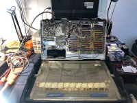
Chassis-up.jpg

And this revealed the date this machines chassis was build, September 5th 1970
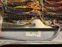
Inspection-label.jpg

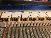
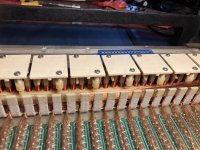
And while I have the thing apart completely, I opened up the plastic cover for the ROM and took some shot of that. I couldn't see anything obviously wrong with it... but it does look very nice, odd to think that this is what holds the microcode for the system.
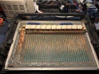
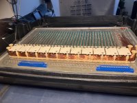
ROM1.jpg
ROM4.jpg
ROM6.jpg
ROM5.jpg

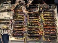
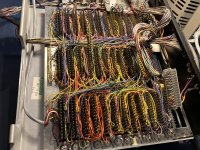
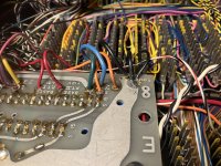
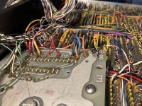
And also some shots of the wiring side of the chassis
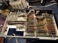
Chassis-open1.jpg
Chassis-open2.jpg
Chassis-open3.jpg

A couple of minor things I did notice, there was a pin on one of the connectors on the back plain that is filled up all the way with wires and it was a bit bend over. It wasn't touching anything now, but my guess was that it might have also been a bit crooked on the card side causing a bad connection.
There was also some webbing and a dead insect/spider in the ROM connector underneath the PSU... and one of the pins on the little connector board that connects into the ROM board from the chassis is a bit discoloured. So there might've been a bad connections there. Also, in my machine at least, the connectorboards that go into the connectors on the ROM board are a little smaller then the connector they slot into. They are all making a connection though, but they were a bit shifted over so I wonder if every connections was as good as it should be.

Otherwise, everything seems to be very nice inside.

The underside of the PSU looks like it has been repaired a few times (or... the fan on the back was hacked in later). I can see that the heat from the diodes is clearly discolouring the PCB of the PSU. But, as far as I can tell from previous testing, the PSU isn't doing anything weird at the moment. I might still reflow a few points just to be sure.
 
The underside of the PSU looks like it has been repaired a few times (or... the fan on the back was hacked in later). I can see that the heat from the diodes is clearly discolouring the PCB of the PSU. But, as far as I can tell from previous testing, the PSU isn't doing anything weird at the moment. I might still reflow a few points just to be sure.

No... thinking about it, they did not hack anything in. It's a US build machine that was later converted for our 220V/230V power grid. I've never actually measured the voltage on the fan or the tape drive motor... I guess they should still be 115ish V. (The back of the machine even still says 115 V 60 Hz near the power switch).

I did not do anything to the PSU yet, but did clean the connections between the ROM board and the rest of the chassis. It did not change the behaviour. It does seem that some of the weirdness is caused by "flexing" the inner chassis (with the chassis unbolted from the main shell, I can replicate the weird behaviour by moving the chassis instead of the shell, this means that the ROM is not moving, just the card cage and PSU).
At least nothing got broken any further... and it may or may not have narrowed the search area down a little.
Also, I now know how to get it apart, it is a bit fiddley, but not nearly as bad as I first thought.

Also, I was looking at the pictures I took of the PSU and may have missed a bad wire going to the back plain. One of the black wires seems to have a bit of isolation melted off and it almost seems a bit greenish (hard to see though on the picture). It got my dayjob brain active as it looks a lot like a wire from a mains switch box or distribution board that is not connected properly and is heating up due to that.
Now I did measure the resistance between the PSU and the back plain and it was 0.0 ohms, but if this connection is getting hot it can go high resistance over time.
I guess it's coming apart again soon.
 
I may have found something.

Bad-connection.jpg

The middle black wire on the 0V plain is not connected very well. I traced it to it's destination (a pair of caps underneath the back plain near the voltage regulator on the back of the machine) and if I wiggle the wire while beeping it out with the multimeter, the connection breaks. Not an easy wire to fix though, although I might as well solder it to the big ground plain there...

Edit:


a-bit-fixed.jpg
Getting that wire attached well again did solve some issues, but not all. It still won't behave past 185 V AC from the mains. And it can still behave strangely when the right and left corners of the case are lifted up slightly, putting pressure on the inner chassis. I might have another look next weekend, as there could be more connections there that are not quite well attached.

That said, I can now program the memory again from the keyboard. Which I'll take as a win for now.
 
Last edited:
Having the whole thing apart again, I took a good look at where the 2 rectifier diodes are for the 5 V supply... they look all dull (opposed to the nice shiny look of the 12 V diodes which should be the same). The 5 V diodes are getting really hot and there is actually a near black patch underneath on of them (the entire PCB material looks crispy, even from the other side of the PCB).
I did reflow most of the outgoing wires, just to make sure they are all connected properly.

I wonder if one of the problems, the fact it needs to run on a lower AC voltage, has to do with either 1 or 2 beginning to fail diodes or that the carbon track underneath one of the diodes is conducting some AC across. Making the unregulated side of the 5 V supply iffy, leading to whatever is connected to it misbehaving.

These old diodes are available on ebay... and not even the most expensive thing to order (I'd like to keep things original if possible) but I wonder if it's better to use a diode that can handle a bit more amps. These are 50 V 3 A diodes, maybe a 4 A or 5 A would be better?

I also need to try and get access to them and see about getting rid of that carbon patch under the diode.
 
Back
Top