• Please review our updated Terms and Rules here

Wang Series 700B Advanced Programming Calculator Refurb.

The weird thing is that those "ceramic disc" components don't seem to be on the schematic, the resistors and diodes are accounted for. Are you able to see any markings on them? I'm wondering if that one diode on the "bad board" was a field replacement that was wrong. It would help if you could see the traces and find out how that component fits into the wiring. Adding to the mystery, the schematic implies "rev 7" but the board says "rev 4".
So, I'm doing this of the pictures I took while taking the machine apart last time. My best guess from looking at those, and the traces on the front and back of the boards, it's most likely the diode at D6 called D1 (which is a 1 of 1 in those boards). I'll have to take them out and see, also for numbers. Looking at the back picture that diode is a replacement, I can see it's been reworked.

Also, and correct me if I read that wrong, the schematic says it has a total of 35 diodes. On the board with the odd diode I see 17 "glass" diodes, 5 "Blue" diodes, and the weird black 1... I'm obviously missing something, I guess some of the diodes look like resistors at a glance?
Although I should have a few less diodes as I have the 74141 so that bit in the dashed line box is not on my boards.

Hmm, I'm creating more questions then answers this way, I'll take some stuff apart tomorrow and try to get some answers and go from there.
 
Best I can tell, there are 12 general purpose diodes not populated (on schematic but not on boards), plus one zener. See the "DO NOT LOAD" section. I am wondering about those components that look like resistors on the Y board but are glass diodes on the X, that seems strange. They definitely look like resistors on Y, and it is possible that they waffled between whether those need to be zener diodes or could just as well be resistors (they are just biasing the transistor base, so maybe resistors work just as well - and are cheaper. D1 on the schematic is a 60V zener, so wondering how that could be replaced by a ceramic disc capacitor. But, zeners can definitely go bad, or overheat if there is too much reverse-current. The odd thing is that D1 is part of the DO NOT LOAD circuitry, so I wonder why it is populated at all. We may be dealing with a case where the schematic does not match the board(s) and so we're scrambling to make meaning of it.
 
Oh, now I better understand that part of the schematic. So you either have the 74141 or a bunch of diodes and transistors to drive the nixie cathodes.

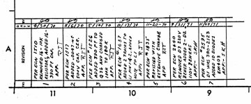
I did find the caps on the schematic though, they are a little bit hidden. They are mentioned in the revisions section on the lower left of the schematics for both driver boards.
caps.jpg

There were 16 added somewhere at revision 1 (which would be the 16 caps above the transistors on the board I guess) and 1 at revision 3 near Q36 (which is only fitted on my Y board.

They also added a 500 V 0,0047 uF cap somewhere at revision 2.

If they used resistors instead of zener diodes to bias the transistors, that might explain why one of my Y tubes had trouble striking? If the baising is wrong due to a out of spec resistor. I also noticed there is an extra transistor on the Y board that is not on the X board (although there is a spot for it, but I don't think it was ever populated) which is not on the schematic at all. It's between Q31 and Q34 on the layout drawing in the schematics and is connected to Q34 in some way.

Would it be possible to start the machine up with only 1 display register installed? If it works "fine" on one display card, then we have at least isolated the problem to the X register card.
 
Quick update, I took the 2 display card out and looked them over. One of the solderjoints on the back of the Y card isn't very nice, but should be connected.
The Y card has no zeners on the anode drivers, just resistors. All diodes that I could identify test "fine" in a multimeter diode test (aprox. 0,6 volts one way, blocking the other). The resistors on the Y card that are zeners on the X card measure as 182 kOhms ish in circuit.

The cap on the Y board that is a diode on the X board is the 500 V cap as per Revision 2... it's marked Z5U 4700M 500V.

Looking at the X board there is evidence of rework at more then 1 place. I don't think the extra transistor was ever fitted here but the 390pF cap from Revision 3 was removed. Instead of that extra transistor and some resistors, the X card just has a "Blue" diode.
I'll investigate that with the schematics this afternoon... but I get the feeling that the extra transistor has something to do with the fact they used resistors for biasing the rest of the card instead of zener diodes.
 
Going over the boards in more detail with the schematics open I think I may have spotted on oopsie from someone long long ago...

Possible-oopsie.jpg

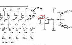
I drew in the possition of the 500 V cap that should be at the spot of the diode, I think from it's possition it's just a decoupling cap for the + high voltage for the screen after Q34.
My guess is, that someone at somepoint put either a normal diode or a D2 zener diode there as per the red circled area.

Now (and this is theory crafting but still), what if this diode has been slowly dying over time (because it really shouldn't be there) and by doing so, it's ever so slightly pulling up the 0 V rail throughout the machine. Causing ever increasing mayhem across the various TTL chips that need that +5 Volt to be stable. And yesterday it came to the point where the machine can no longer work in a stable fashion because it's +5 volts is no longer stable.
Basicly, if this diode would short out... the + 250 Volts would short to 0 Volts and heat the diode up... but only as much as transistor Q34 could handly currentwise.
This diode slowly breaking down and messing with the TLL logic might explain another quirk or 2 this machine has that I always atributed to a slightly marginal filter cap in the power supply.
 
Ah, yes, read the change-log! In cases like this, having those ECNs would be a goldmine. I wonder if some old Wang tech has those but never scanned them, thinking the schematics were enough. Or else the person that inherited the schematics from a departed Wang tech did not think they were important. Who knows.

Some of the bad behavior you describe does sound more like its coming from other parts of the logic, not these display driver boards. So I'd definitely look for the reason that the +5V is out of spec. I'm not yet seeing how these anomalies with the X and Y boards would drag down +5V, though. Something sapping the 250V rail would probably be isolated from the +5V, due to the voltage regulation circuitry. I'm not even sure where the 250V comes from here - it would have to be off a separate winding of the transformer.

I haven't found any difference in the schematic between the X and Y, aside from the note about whether bus pin 4/1 is used. Looks to me like they could be interchanged without issues. Also, running with only one seems fine as well, the other bank of nixie tubes simply won't get driven. And it looks like all bus connections are inputs, so there is nothing being driven out to the rest of the calculator. Wang draws their circuits in a weird way (to my eyes) - especially when discrete components are involved, and I often have to go redraw a section in order to understand it. I had to do that to understand the keyboard enable logic.
 
ome of the bad behavior you describe does sound more like its coming from other parts of the logic, not these display driver boards. So I'd definitely look for the reason that the +5V is out of spec. I'm not yet seeing how these anomalies with the X and Y boards would drag down +5V, though. Something sapping the 250V rail would probably be isolated from the +5V, due to the voltage regulation circuitry. I'm not even sure where the 250V comes from here - it would have to be off a separate winding of the transformer.

The reason I had this thought is, there is only one 0 Volts connection on this board. And both the + 5 volts and the + 250 volts are connected to it in some way on these cards. The + 5 Volts via the larger decoupling capacitor and the 74141. And the + 250 V via the 0,0047 uF 500 V cap that should be at the diode. It's annoying that these caps are not on the schematic, that would have made this a whole lot easier to figure out.

I fully agree with you that this is odd and not what one might expect here, but I beeped it out on both cards and that same 0 V connection coming from the card edge is connected to the 0 V of the chip and the 0 V side of the cap. EDIT: ok I lied, there are 2, but they are connected on these cards, they're not 2 sepparete 0 V connections.

I had a bit of rummage through some boxes of junk power supply boards. I have a few ceramic disk caps on those but they are 222K, at 1 kV. Not sure if that is a suitable replacement. I might order a few correct caps anyway and maybe even look to see what equivalent diodes I can find just to be sure and have some spares.
 
Are you certain that "222K" isn't the value, not the voltage rating? I seem to recall values being stamped like that on disc caps, and the "K" might indicate voltage or temperature or some other part of the rating. In my recollection, the "222K" would translate to 2200pF with a voltage/temp/??? rating of "K" according to some standard.
Yep, that is what I meant, 222K is the capacitance and 1 kV would be the voltage.

I have the machine running on 1 display card but it's not entirely happy still. I always run the Wang through a variac and a breakerbox with a 1 amp breaker. This also gives me a test point to measure the mains voltage. Since I have solar panels the supply voltage can go pretty high, easily up to 245 V. So I always monitor the voltage that I send into the machine when I use it.

It's currently running on 1 display, but I can't increase the voltage past around 190 V AC. Beyond that if will go haywire in a similar fashion as it did with both display cards fitted (I put the Y register card in the X location now btw). But around that 190 V AC it's doing calculations just fine (just need to arrow down to see the result) which is a bit odd...
I can even load a program from the laptop using that cassette tape adapter.
 
The reason I had this thought is, there is only one 0 Volts connection on this board. And both the + 5 volts and the + 250 volts are connected to it in some way on these cards. The + 5 Volts via the larger decoupling capacitor and the 74141. And the + 250 V via the 0,0047 uF 500 V cap that should be at the diode. It's annoying that these caps are not on the schematic, that would have made this a whole lot easier to figure out.
...
After re-reading your post, fully this time, I see my comment about "222K" was incorrect. So you are asking about replacing a 4700pF cap with a 2200pF? I guess we could look at the refresh rate (frequency of the anode/digit select signals) and see if this cap is meant to filter out that or not.
 
After re-reading your post, fully this time, I see my comment about "222K" was incorrect. So you are asking about replacing a 4700pF cap with a 2200pF? I guess we could look at the refresh rate (frequency of the anode/digit select signals) and see if this cap is meant to filter out that or not.

I can harvest 2 out of the old PSU... So it could be a 4400 pF at that point.
 
Regarding the 2200pF cap, if you have two of them you can wire them in *parallel* and get 4400pF which is probably close enough to 4700.
 
So, the fact that it is running on a mains voltage of 190 is an interesting clue. Not sure what it means yet, but I think it is telling us something. Firstly, the +5V regulation circuitry must be pretty darn good! But if the +5V rails goes lower when the input voltage goes higher, that's strange. But, it could be related to things like zener diodes that start to draw too much current as the input voltage increases, and might be having an effect on the output. Getting a look at the +5V rail while you increase the mains voltage might be helpful.
 
... also, though this is probably unlikely, could something have affected the transformer such that it is no longer producing the correct voltages on the secondaries? If some of the primary coils shorted, that would increase the ratio of windings and increase the voltage on the secondaries.
 
So, the fact that it is running on a mains voltage of 190 is an interesting clue. Not sure what it means yet, but I think it is telling us something. Firstly, the +5V regulation circuitry must be pretty darn good! But if the +5V rails goes lower when the input voltage goes higher, that's strange. But, it could be related to things like zener diodes that start to draw too much current as the input voltage increases, and might be having an effect on the output. Getting a look at the +5V rail while you increase the mains voltage might be helpful.
Yep, the 5 V regulation is pretty good. At 160 V AC it's at around 4,6 V. At around 175 V AC (when the nixies kick in) it's at 4,75 V. Increasing it from here slowly makes it go all the way to 4,86 V at around 220 V AC. This is, btw, on a cap on one of the cards, not on the display card.
The voltage on the cap that sits between Vcc and Gnd of the 74141 is 3 V at 160 V AC and 3,6 V at 180 V AC and around 4,16 V at 220 V AC. There is a diode before my measure point though, so there should be some voltage drop there.
 
... also, though this is probably unlikely, could something have affected the transformer such that it is no longer producing the correct voltages on the secondaries? If some of the primary coils shorted, that would increase the ratio of windings and increase the voltage on the secondaries.

I wouldn't know what... this machine sits at a spot on my standing desk and is only rarely moved. I just power it up every now and again to make sure it works, run a few programs, zero out the memory again and turn it off.
 
I wouldn't know what... this machine sits at a spot on my standing desk and is only rarely moved. I just power it up every now and again to make sure it works, run a few programs, zero out the memory again and turn it off.
Yes, but you mentioned that you mains voltage can run high some times. If there were a weakness in a transformer winding, that's the kind of event that would break it.
 
Yes, but you mentioned that you mains voltage can run high some times. If there were a weakness in a transformer winding, that's the kind of event that would break it.

That's why I always run it through a Variac, maintaining around 220 V to 230 V. I never plug it directly into the mains. Also because the caps in the main PSU are old and hard to reach. So I always bring the supply up slowly when I haven't used it in a while.
 
So, probing the actual +5 V on the connector is a bit hairy, as the + 250 is right next to it... but I did it and low and behold this is odd. This should be connected to the + 5 V R (the regulated supply) and thus I expect it to be at around that 4,75 Volts that I got somewhere else... but it's not, the + 5 Volts there is around 4,2 Volts (with the supply voltage at 180 V AC) which is really low. Increasing the supply voltage beyond 200 V does make this point go up to 4,85 Volts

I'm not entirely sure BTW what + 5 V I was measuring on the main cards... But I doubt the unregulated 5 volts would be more stable then the regulated one.
 
Back
Top