• Please review our updated Terms and Rules here

Commodore PET CBM 4016 ASSY 8032080 RIFA burn and more

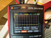
I measured UB2/11 because I tried the traceback as per your recommendation of J7/1 and it was one of the few non-constant signals.

this is the zimmer pet 8032 section and i do not find my assy there unfortunately. most files are uncommented and all carry the wrong number.

IMG_9733.jpeg
 
ah nice - while zimmer is a hero for giving us the schematics - the site is terribly organized for someone without already knowing all the different models etc
 
Last edited:
ah nice - while zimmer is a hero for giving us the schematics - the site is terribly organized for soneone without already knowing all the different models etc

That is not Bo's fault - it is Commodore's...

There is a part numbering scheme. The number on the PCB is the PCB assembly. The schematic then follows on numerically.

Dave
 
well my board assy started with 8032, so it never crossed my mind to look in a folder called univ... the 8032 folder seemed just right...
 
CK is the clock pin. If you check the data sheet for the IC it will tell you how the chip works.

A sine wave is as good as you will get. It may also be the bandwidth of your oscilloscope. Are you using a X10 probe setting? If not, you may be reading the signal incorrectly.

Is there a clock here or not?

My train of thought from your post was that UD4/13 was LOW. This led me to UC1/5. You need to measure all of the pins of that gate next.

Dave
 
Yeah I'll do more tomorrow. Turns out in the zimmer univ folder there is no schematic for 8032080 but it links to 8032029 - thats what bottom right says on pages. so i have been on the right schematic, correct? good night for today and thanks so far, alex
 
Err, I don't think you understood what I posted.

The correct assembly diagram for your machine is the 8032080-n.

The correct schematic diagrams for your machine is the 8032081-n.

If you look at 8032080-2 you will see:

Item 1 is a PCB part number 8032079.

Item 2 are the schematics part number 8032081.

Dave
 
Last edited:
what is the issue with the white guys? do the legs break off? or do they make bad contact? i pulled both put and back in already... cpu was very tough
Are you saying that you removed the sockets and re-fitted them, or removed the IC's from the sockets and re-fitted them ?

The white sockets can be ok, but the design is not very reliable because they are a single wipe type. There is only one metal leaflet that wipes one side of the IC pin, not the customary dual wipe type. However, if the socket's pins have a strong tension and they are clean, and the IC pins clean too they do make a good contact. I still have these in my PET and so far I have not had to replace them.

If you ever removed a white socket though, it would be ill advised to put it back in, much better replaced with a modern dual wipe socket. The most important part to preserve is the pcb itself.
 
@Hugo Holden Aren't you supposed to sleep? :) I just pulled the ICs out, cleaned around the contact areas of socket and ICs and put them back in. Good insights on the white sockets! You always seem to know some amazing details...

@daver2 :'-) No I absolutely did not understand what you meant until now. So I was supposed to look for my 8032080 schematic in a folder called univ. Then, after 8032080-1.gif held no helpful info, I should go to the next file 8032080-2.gif. This one includes electronic parts and the schematics are listed as a part (???). Ok so this means I need to use the 8032081 as my correct schematics. Wow. Also, my PCB in the parts list is called 8032079 even though it has 8032080 printed on it... Holy moly... I think without experts like you this feels impossible to conclude naturally. I fixed a lot of IBMs before and Commodore has made a total mess here.
 
Nope, standard fair. DEC do exactly the same, as do Intel.

The blank PCB is one part number, each component has a unique part number, the final assembly (PCB + components) has a part number etc.

Dave
 
Alright. Guess I have nothing to do with the industry so at least it is new to me. Maybe someone (or even an AI scraping stuff) else will find it useful one day.

So I msged someone to burn me a 2716, also I think I might have reach that EPROM burning capability also shortly. I am afraid I can not successfully do tweeking to the ROM image. I have no clue what to do with your table in there for my 4032 50Hz. Could you provide an image to burn please or explain what changes and process needs doing?
 
A good reliable programmer, that can do the 2716, that is very easy to use is the GQ-4x, these are readily available on ebay. A hex editor program is also helpful for manually modifying byte files too.
 
It looks like the 'magic' is taken care of by the universal board links as opposed to the CRTC programming.

What EDIT ROM part number do you have fitted? I can check my PETTESTER programming against the EDIT ROM.

However, as an initial test, I would test with the monitor disconnected and ensure that the HDRIVE and VDRIVE signals being generated by the CRTC match when the PET is running with its own ROMs and with my PETTESTER.

Dave
 
I got a tll 866ii plus eprom burner and apparently if you crank up vpp to 21v with a bench power supply it can do the trick. it is just opening another can of worms that id rather avoid - if positive reinforcement is staying absent i will likely just sell the pets without board - should work ideal for mini 40 or such as keyboard monitor and case are almost mint. i actually own a pro log m900 eprom burner from the 70s based on a 4004 (for sale to fund my other retro invests) but i got no way to get the data on that heavyweight. i am missing the actual eprom ics and a uv light. and i am not very interested to learn how to compile assembler as of right now.
 
CRTC pin 39 has action pin 40 is flat as per images
 

Attachments

  • IMG_9754.jpeg
    IMG_9754.jpeg
    160.7 KB · Views: 3
  • IMG_9753.jpeg
    IMG_9753.jpeg
    166.2 KB · Views: 3
Back
Top