• Please review our updated Terms and Rules here

Commodore PET CBM 4016 ASSY 8032080 RIFA burn and more

Is there an easy way to get a PETTESTER in the mail in the EU? Or is it get a EPROM burner, get EPROMs and DIY only? And I got thermal imaging :) I am waiting for the moment when that investment helped me fix a problem. Still waiting. Thanks, Alex
 
Last edited:
If you post in the "vintage computer services wanted" section for some kind person within your region to burn and ship an EPROM to you for money - I am sure that can be arranged.

Alternatively, you could purchase Bitfixer's or Nivag's ROMulators that can replace your ROM and RAM, have an inbuilt NOP generator and contain a number of diagnostic test tools (PETTESTER included).

One of these tools will be invaluable for fixing more complex faults with stubborn PETs.

Dave
 
Thanks I will check both options out tomorrow. For today I am focussing my detective work on the non-randomness of my garbled screen (as i can do this immediately). Seems every second column prefers inverted characters. Also, what problems do I not have to worry about when I hear the chirp? I guess frequency generation, CPU is fine... Also wanted to mention that I wrapped the fixed trace with electrical tape as my solder job was inferior. Best, Alex
 
If you get a chirp, the CPU is fine - as is part of the VIA and there is enough ROM and RAM working.

However, you are only checking out a small percentage of the machine. Still, it is encouraging.

Dave
 
Small update so I think there is more than one thing wrong.

Basically: garbled screen, black screen, black screen with ultrabright dot in center are all possible power on - outcomes. They do vary likely with temperature and power cycle pattern.

Also Chirp only happens very rarely even when visually the best outcome the garbled screen is there.

I wanted to remove and clean all the socketed chips. The 6502 feels inpossible to remove from the white socket. if i use any more force it feels something will break.

I will do a board swap to test keyboard and monitor assembly later. Board power lines i will check first. Pre Pettester are there any lines to check on the troubled board with osziloskop to narrow issues down?
 
Yes,

6502 CPU pin 7 (SYNC). This should be pulsing HIGH if the CPU is executing instructions.

Measure the VIDEO, HDRIVE and VDRIVE signals from the PET logic board to the monitor with something on the screen. This is to get a reference for what "good looks like".

If you get the spot in the middle of the screen - turn the brightness control right down if you can (to prevent burning the screen) and measure the VIDEO, HDRIVE and VDRIVE signals again from the PET logic board to the monitor.

If these signals are running correctly, the problem is within the monitor.

If the high voltages are there (i.e. the spot stays around for a long time - but PLEASE PLEASE ensure the brightness is turned right down to prevent burning a spot in the middle of the screen) it is likely to be cracked solder around the connector pins between the monitor PCB and the scan coils. That is where I would look anyhow to start with...

Dave
 
Thank you Dave, I will get right to it! So far I immediately turned off in the bright dot scenario. It was sooo bright that screen damage seemed imminent. it never hit the center more than 2-3 sec continuos.

i have done the mainboard swap and am happy to report that monitor assembly and keyboard are without noticeable issues

Ok, 6502 pin 7 signal is hereIMG_9552.jpeg

i dit try to measure anything on video connector J7. All voltages are flat DC except leftmost single pin which looks a mess:


IMG_9554.jpeg

i realized i actually have an eprom burner but no eprom ics... thanks
 
>>> it never hit the center more than 2-3 sec continuos.

I am not sure what you mean by this. Did the spot only last for 2-3 seconds before it went out or what?

The signal on the SYNC pin is good. It is executing instructions.

When measuring the signals on J7:

1. Where is your oscilloscope ground connection?

2. Under what circumstances were you measuring these signals? With the screen working or not?

Dave
 
regarding spot: i immediately turned it off - it was sometimes drifting slightly left and down - monitor confirmed good due to alternate board test

during J7 measurements i grounded on case. i think the single pin on the left that i measured is supposed to be ground and pin 7. so i measured ground vs ground. will redo.
 
Last edited:
J7 pins 1 3 and 5 in that order (screen likely black but not connected) it is all 5v...
 

Attachments

  • IMG_9569.png
    IMG_9569.png
    323.7 KB · Views: 1
  • IMG_9570.jpeg
    IMG_9570.jpeg
    2.6 MB · Views: 1
  • IMG_9571.jpeg
    IMG_9571.jpeg
    2.6 MB · Views: 1
  • IMG_9572.jpeg
    IMG_9572.jpeg
    2.7 MB · Views: 0
ok now i played powercycle madness until i got a garbled screen - it is very rare - like 1 out of 20 power ons. i then unplugged j7 and measured: j7 pins 1 3 5 :
 

Attachments

  • IMG_9574.jpeg
    IMG_9574.jpeg
    2.6 MB · Views: 1
  • IMG_9576.jpeg
    IMG_9576.jpeg
    2.5 MB · Views: 1
  • IMG_9577.jpeg
    IMG_9577.jpeg
    2.7 MB · Views: 1
So, those oscilloscope settings and what you observe look correct.

When the screen goes 'faulty', do these signals all go away? If so, the problem is the logic board.

Dave
 
what i take from that is that there seems to be at least two problems: first problem is intermittent in the video circuitry that pulls all signals to 5v. Second problem makes screen clear routine unsuccessful - could be anything dram vram logic...

sorry for careless writing as i do most of this on the workbench on the mobile while juggling stuff. please don't be offended for grammar :)

i do have 2 spare good 4116 sitting around, but piggybacking seems to be an option only after i get a reliable video output, right?
 
Yes Dave, if the screen goes faulty I get 5V DC on all J7 pins 1 3 5 as per screenshot of osci above the above. and yes problem is definitely logic board only.
 
Both of the faults could be linked.

No problem with the grammar! I just want to ensure that I am understanding correctly what you are saying.

Dave
 
Any ideas on what to measure on the board to narrow down the cause for the broken video signal? does intermittendness point towards a trace / solder issue vs a cap / ic / diode failure?
 
Yes...

If the video signal disappears then look at schematic https://www.zimmers.net/anonftp/pub/cbm/schematics/computers/pet/2001N/320349-8.gif.

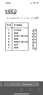
Work your way backwards from the video signal (J7/1) a gate at a time looking for pins that would cause the observed effect and then work backwards from that to the next gate and so on...

The first gate is G11 pin 6 and the input pins 1, 2, 4 and 5.

A NAND gate has a logic '0' output if all of the inputs are logic '1'. If you are seeing a permanent '1' here then we need the output to go to a '0' so all of the inputs are required to be coincidentally at a logic '1'.

G11 pin 1 is connected to +5V - so it is worth checking this to see there is a logic '1' actually there...

Likewise for the other G11 input pins on this gate.

If you see an input that is permanently '0', the output from G11 pin 6 can NEVER go low - so this is your first step in finding the fault.

If all of the pins are oscillating (well, the ones that are not tied to +5V) and the output never goes to a '0', it could be a faulty IC or it could be that the inputs are not all a logic '1' at the same time.

The only way to determine this is to use a multichannel oscilloscope on each input, a logic analyser - or use a 2 channel oscilloscope and try to get a trigger signal to observe the multiple inputs at the same point in time - but a pin at a time.

Let us assume that the fault is a 'stuck' input first...

Dave
 
Oh well.... I think I am going to give up on this one. Too much time for little progress. These schematics tend to not help me. I don´t know where to find G11 and all its input on the PCB board. So traced J7/1 and the only connection I found is to the last PIN of UC2. But then I can`t find what UC2 is in any schematic. Then UC2 is a 74LS86. I dug out the datasheet and it does some XORs. Puh. The schematic you posted has a hint showing G11 to be maybe in a 74LS20. But there is no 74LS20 anywhere to be found on the darn PCB.

I dug out another blackscreen PET and it turns out its got a flat 5V on J7/1 as well. This seems to be a common thing. But of course it is another motherboard revision.

Should I even try to source a PETTESTER? With no screen will it be helpful? What kind of ROM do I need to burn it btw. Where can I find the documentation?

Thank you Dave though for helping. Learned a lot.
 
Last edited:
You are giving up a little too early I think...

First thing, do we both have the correct schematic and PCB layout? If not, I am talking apples and you are looking for oranges...

The Commodore Pet PCBs are laid out in a grid, so G11 should be easily identifiable...

We may be using different schematics (for different machines) - which doesn't help!

On this schematic: https://www.zimmers.net/anonftp/pub/cbm/schematics/computers/pet/univ/8032081-08.gif the ICs would be UC2 and UD4.

If ANY PET has a black screen (assuming the monitor is good), you will most likely have either flatlined video signals or the random screen. That is the nature of the fault... It does, however, depend upon the particular PET of course and whether it has a CRTC or not.

You need either a 2716 or a 2516 too burn my PETTESTER into. It replaces the EDIT ROM at a base address of $E000.

The link to the source code, HEX and BIN files and the documentation is here: https://drive.google.com/drive/folders/1fyLbr1kcG98a2FDOMo1H5pj9lIdJpHcx?usp=share_link.

If your PET is a 40 column machine with a CRTC, then some tweaking to the CRTC initialisation is required. For 80 column PETs (with a CRTC) and non-CRTC PETs you are good to go.

It is not much use if the screen is not working I am afraid...

Dave
 
Last edited:
no worries, I think you had me looking at the wrong schematic and I didnt realize. I was hoping the assy identifies the version. I find zimmers hard to navigate - i never find the right files. if somebody with more knowledge than me could put some context around them it would be far more accessible

i will order a 2716 and hope the tl 866 can burn it. i also piggybagged a 4116 around all 8 dram slots with no effect. i checked the reset pin on the 6502 and it comes high after a while. i also oscilloscoped all voltages in the red area of the image.
 
Last edited:
Back
Top