daver2
10k Member
So there is no 16 MHz clock then!
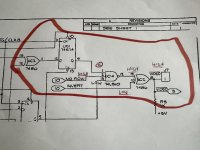
Check UE5 pin 6 (74LS00). This should be a 16 MHz signal.
Then check UD2 pin 10 (74S04). This should be either 8 MHz or 16 MHz - depending upon the setting of link J1 or J2.
By the way, I am on this schematic now: https://www.zimmers.net/anonftp/pub/cbm/schematics/computers/pet/univ/8032081-06.gif
Dave


")