• Please review our updated Terms and Rules here

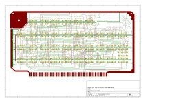
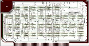
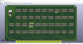
Cromemco dazzler replica project

Learning as I go, the point about the Via's was well made, many are just that but a lot are component mounts and my holes are indeed too small. Simple matter of setting the default, but then I run into problems with clearance.
Will just manually go through and change the ones that have things stuck through them.

It is interesting to me, the way it was assumed by some that the replica Dazzler pcb's I designed and had made by LD Electronics seemed "over priced" or maybe not good value. But it appears everyone wants a bargain, despite the price of Gold.

Part of that assumption comes from the notion that we have almost been schooled to believe that you can whip up pcb's, in a pcb drawing program and have them made by an off shore pcb house, for a small cost.

But there are so many traps and tricks to getting it right, especially for the boards like the Dazzler if you want a decent replica.

The track-work has to be perfect, the board perimeter and finger geometry perfect, the taper on the the board edge leading to the fingers so it will plug into the edge connector with minimal initial force. The pcb via holes and other hole geometry important, the board surface ink markings, the Gold plating etc. It all adds up, possibly to more than the sum of its parts, as is the case with most things that turn out well.

Daver2 has a pair of the boards that were made by LD. He could therefore provide an objective opinion of what he thinks of the quality of them and if they might be value for money, or not. Rather than me sounding like a biased lunatic saying they are good value.

The thing is, as you are finding out for yourself, there is an awful lot of detail in these Dazzler boards. I had to find that out for myself too, starting from scratch and the faded foil diagrams.

But, it is great you are working through it, much like I did.

On some projects I do sometimes wonder if I'll ever get to the end of it, if I am half way through it. But, if you keep working hard, and burning that midnight oil like I did, you will get there and that is a great feeling.
 
I agree, but part of it is the journey. If it doesn't get to the end, then ah well.

I did get a good quality A1 PCB for significantly <£100 so manufacturing cost of a PCB is only half the story. I bet if you factored in your time at commercial rates it would be even more expensive.

(BTW, does a dazzler work in a NS Horizon anyone ?)
 
Last edited:
I did get a good quality A1 PCB for significantly <£100 so manufacturing cost of a PCB is only half the story. I bet if you factored in your time at commercial rates it would be even more expensive.
Actually well under half the story. If the hours, days & weeks that I spent on it, if they were were charged out at commercial rates, even very modest ones, it would easily have hit $10k or more. A good thing I did it for the fun & enjoyment of it only.

When I built Martin Eberhard's ME5204 vintage Eprom programmer, I wondered how much that machine could have cost to initially create starting from scratch, if it was billed out by a Corporation at standard rates. It was the same standard of work that a team of people in a large company might have done, circuit & pcb design & manufacture, a detailed BOM, perfect firmware development, very detailed manual, mechanical engineering design etc. I doubt if you would come out of that for less than $30k, probably more. Good thing he did that for the enjoyment of it and to help others.
 
Last edited:
Hugo - I've taken the plunge, and ordered the board set from LD Electronics.
You mentioned that for "period consistency" you used Augat machine pin IC sockets. These are now only available as "new old stock" and are no longer being manufactured by the company (TE Connectivity) that owns the former Augat product line. Do you recall which shop you acquired your Augat sockets from?
I think I got them from various ebay sellers at the time as I recall.

But, I also noticed recently that a very trusted seller, I often buy parts from him, his name is Dinos and the ebay seller ID is Qservice-electronics, has these lovely Augat sockets as they are used in Tek scopes, and he supplies parts for these.

These are the 16 pin ones, so if I were building another I'd get these:


I'm not sure if he has the 14 pin ones though. It would be worth asking him, he has lots of things.

These 14 pin ones look ok if Dinos dos not have the 14 pin variants:


One advantage of the all Gold Augat socket is that even if they are old stock the pins are not as subject to corrosion as Tin plated ones, so generally they solder very well, unlike aged Tin plated ones which can give significant trouble, so it is not as important that they be new manufacture as it is for the Tin plated ones.
Thanks Hugo. I need to re-think how badly I want to replicate your build using period-correct IC sockets. No single vendor has both 14 and 16 pin Augat sockets in stock, and no single vendor has enough of either type in stock to supply the number required... so the cost for just the Augat sockets plus shipping is currently somewhere around $US 300. I may just settle for good quality gold machine pin sockets that are in current production.
 
Hugo - I've taken the plunge, and ordered the board set from LD Electronics.

I'm going to chuck this out as a standing request for anyone that manages to get a replica Dazzler running (or has an original, for that matter): I'd love to see some photos of how it looks on a digital TV and/or monitor via composite->digital converter. Devices from this era that did interlace (and that use such relatively simple video hardware) are vanishingly rare and I'm curious how modern equipment interprets it.
 
I'm going to chuck this out as a standing request for anyone that manages to get a replica Dazzler running (or has an original, for that matter): I'd love to see some photos of how it looks on a digital TV and/or monitor via composite->digital converter. Devices from this era that did interlace (and that use such relatively simple video hardware) are vanishingly rare and I'm curious how modern equipment interprets it.
Sound like a good plan.

Prior to making my Dazzler I did see one for sale, the full board set and I think it was NOS, it sold for around $1000 USD as I recall, it might have been $1100. So it does make the $500 about USD for the replica bare boards from LD seem reasonable. Maybe if more people buy and make them we will get an answer about the modern equipment and Dazzler signal tolerance.

Because I went over the Dazzler circuit very thoroughly , I found & documented all of the unused gates in various packages, there are a good number. So it would likely be possible to use some of these (much like I did for the case of Pong and its bugs) to eliminate any issue that affected modern equipment, as a small circuit modification.
 
I'm going to chuck this out as a standing request for anyone that manages to get a replica Dazzler running (or has an original, for that matter): I'd love to see some photos of how it looks on a digital TV and/or monitor via composite->digital converter. Devices from this era that did interlace (and that use such relatively simple video hardware) are vanishingly rare and I'm curious how modern equipment interprets it.
Though the recorded image quality was limited by taking a video of a monitor screen, you can get a bit of an idea of what the Dazzler output looks like when routed through a good quality composite video to VGH converter - see the video at the bottom of this page:
 
First board 'done'


Board 1.jpeg
Still needs lots of work to adjust the via's for component mounting, reviewing to identify errors but its getting there.
 
First board 'done'


View attachment 1247501
Still needs lots of work to adjust the via's for component mounting, reviewing to identify errors but its getting there.


On the face of it it may be ok.

But it is very hard to verify it for errors. I overlaid it on one of my board diagrams previously on the thread that I posted which were a scale copy of Cromemco's work.

On your diagram the aspect ratio is not the same, the IC's are not in the same positions and the tracks don't have the same form.

Doesn't mean it won't work of course , but the problem is it makes it much more difficult to verify it matches the original foil diagram & circuit.

Having said that, it is still very good progress.
 

Attachments

  • Check1.jpg
    Check1.jpg
    295.8 KB · Views: 7
I have found a way to import your images as a symbol to act as a background as I place tracks etc. Should make it easier. Might even redo board one.

Its all about learning too.

EDIT

Oh, that is so much easier. Will redo board one. One thing, the foils show some of the via's with really little holes ? On a picture of a dazzler, they all look about 0.7 ish ?

I also need to redo the socket pads as they are much thicker than the original.

Yay, and now I have found the free track placing so I can make proper track angles.
 
Last edited:
I have found a way to import your images as a symbol to act as a background as I place tracks etc. Should make it easier. Might even redo board one.

Its all about learning too.

EDIT

Oh, that is so much easier. Will redo board one. One thing, the foils show some of the via's with really little holes ? On a picture of a dazzler, they all look about 0.7 ish ?

I also need to redo the socket pads as they are much thicker than the original.

Yay, and now I have found the free track placing so I can make proper track angles.
I suspect that this is how George at LD does it.

The track diagram hole appearances are not representative of their actual size. This was the point of the spec sheet I posted #114. If you look back at the hole specs you will see the vias, IC holes etc are all specified at 0.7mm. It is always good to have big solid vias, many of the default modern via sizes are far too small in my opinion.

It would pay to keep the IC pads as they are on my diagram because they are more robust and would stand up better to repairs (IC or socket removals etc) than smaller ones. Their width was chosen to be as high as possible while still allowing a good clearance for the tracks to pass between them and elongating (rather than just a round or square pad) increases the strength further. Also it pays to have the tracks close in width to what has been drawn and not thinner as they are more robust and better match the original pcb.
 
Last edited:
Yep, going over the trace with everything matching. Done side 1 of board 2. Its much faster this way and much more accurate. Should have something by mid next month :)

1666339536580.png
 
Last edited:
Going very well.

Don't forget not to have any of the conformal coating where the regulator mounts, it increases the thermal resistance to the regulator body & heatsink. Have a look at the photos of the boards on post #1.
 
Yes, I need to work out how to take the mask off in that area, not worked it out yet.

Board 2 is 'finished', but will need 'prettifying'

Board 1 should be layed out end of next week.
 
Last edited:
Both boards now fully laid out.

Need to add the silkscreen for the IC's but cant work out how to do two lines.
 
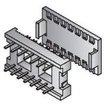
Don't forget, apart from the rare IC, you will need a pair of these connectors for the ribbon interconnect cable, there are very few sellers with these now :


It pays to make a tool out of a pair of plates at least 5 or 6mm thick, or longer than the pins, with holes drilled, 2.5 to 3mm diameter or so where the pins are in one of the plates. The 16 holes can be marked with a prototype pcb board as a template. Then squeeze the connector assembly & ribbon cable together between these two plates in a small vise. This way it avoids any damage to the relatively thin pins on this connector.

Also for the IC socket on the Dazzler board in this location, it is probably better with a dual wipe than a machine pin socket to mate with this connector for multiple insertions. For mine I was lucky enough to have a pair of blue 16 pin dual wipe sockets with gold plated contacts, but these are pretty rare now and I have still not figured out who made them.

This is the variable capacitor:


I'll try to find where I got the Xtal.
 
Hello Hugo, if you need another source for those 16P ribbon connectors I think Mouser sells them "Kobiconn 151-2P16-E" for about $2.00 each.
>> Charles
 

Attachments

  • 151-2P_plugs.jpg
    151-2P_plugs.jpg
    17.1 KB · Views: 1
Back
Top