• Please review our updated Terms and Rules here

Cromemco dazzler replica project

Can you now check that you have a good connection between 0V and +5V for IC46 pins 8 and 16 respectively.
Yep 0V and +5V connections are good

If so, can you replace IC46 - it is probably toast.
I had a few spares, tried replacing the chip but I get the exact same readings on those 4 pins as before.
One thing that seems a little sus though - even though they have the same date markings, the plastic bodies look different.. There's at least 3 different styles here, all with the same markings. Are these counterfeit? They do pass the logic IC tester as 74157's.
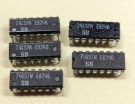
PXL_20240328_185310591.MP~2.jpg

This may account for the completely white screen.
Wait maybe I've forgotten, what should I be seeing with your latest test app running right now? still some pixels in the corner like your first test app?
 
It doesn't matter.

If you are seeing random signals coming in on the earlier step, they should be here...

I am busy fir the next couple of hours though...

Dave
 
It shouldn't matter at this stage whether they are 157 or LS157.

Can you check the 8 input pins to IC46 and see if you are getting the same random data as on the previous steps.

Dave
 
Can you check the 8 input pins to IC46 and see if you are getting the same random data as on the previous steps.

Yep the random data is definitely still there on all 8 of those pins.

EDIT: Just followed all those outputs into IC46 and can confirm the signals are making it to the inputs of IC46.
 
Last edited:
So the 8 bits of 'random' data should go into IC46.

Pin 1 of IC46 selects which 4 of the 8 bits is multiplexed to the output of IC46.

Pin 15 of IC46 (when LOW) should enable the outputs of IC46.

If we have a clock on IC46 Pin 1 (which we did) and a LOW signal on IC46 Pin 15 (which we did) then we should be seeing something on the 4 outputs of IC46.

Dave
 
Just check alled the outputs again, they all look like this.. IC46/4:

PXL_20240328_201535470.MP.jpg

It's not a real clean line when it's high but I don't know if that's random data...?
PXL_20240328_202033929.MP.jpg
 
The random data it should look like is what you posted from step 28.

It should 'swing' from 0V to 5V.

What you are showing me in your second post above is a logic HIGH with a tiny bit of noise on it.

I am guessing the pin goes HIGH when IC46 pin 15 goes LOW (i.e. the outputs of IC46 are enabled).

Dave
 
Yep 0V and +5V connections are good


I had a few spares, tried replacing the chip but I get the exact same readings on those 4 pins as before.
One thing that seems a little sus though - even though they have the same date markings, the plastic bodies look different.. There's at least 3 different styles here, all with the same markings. Are these counterfeit? They do pass the logic IC tester as 74157's.
View attachment 1276696


Wait maybe I've forgotten, what should I be seeing with your latest test app running right now? still some pixels in the corner like your first test app?
Those look like classic counterfeit parts, especially with the identical labels on different IC bodies that have a slightly satin surface and the very shiny pins, atypical for a 1982 vintage part. Still, you cannot be unimpressed with their label machine.
 
It is unlikely that you will have a package from the same manufacturer with the same date code but in different packaging.

They all look suspect I am afraid.

Some have a pin 1 indentation, some not...

Dave
 
So do you think I need to look for replacements before proceeding?

I just found some what look like some good NOS TI parts on eBay.. will have in a few days
 
Last edited:
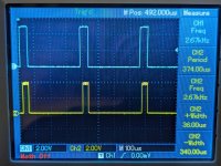
Just one thing to check, it might be nothing, about the pulse that you have CH1 of the scope locked to. Is it still the "T" signal, or was it moved ? One of the recordings showed it around 2.6kHz, it should be 62Hz.

The reason I ask is it is mainly low now on post #667 and we are looking for data that appears when it is high.

But, looking back on post #536 the T signal was mainly high and briefly low and the pulse stream at least was in the high time.

I'm just wondering why the blue trace (scope channel) got inverted or moved ? Both show a non standard for TTL 5V output level.
 
What other devices of the same part number do you have on the Dazzler?
IC13, 27, 34 & 46 are all 74157.
I also got my 7474's from the same seller (which I have ordered replacements for)
They are IC6, 23, 43, 44, 74
 
Just one thing to check, it might be nothing, about the pulse that you have CH1 of the scope locked to. Is it still the "T" signal, or was it moved ? One of the recordings showed it around 2.6kHz, it should be 62Hz.

The reason I ask is it is mainly low now on post #667 and we are looking for data that appears when it is high.

But, looking back on post #536 the T signal was mainly high and briefly low and the pulse stream at least was in the high time.

I'm just wondering why the blue trace (scope channel) got inverted or moved ? Both show a non standard for TTL 5V output level.
Yes it's still on test point "T".

In step 22 you measure T as your channel 2 with a different pin as your trigger. In step 23, you move T to channel 1 and use it for the trigger for future tests.

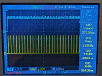
I just tested T again though and can confirm I am measuring T at 2.66KHz. Hmm

Rerunning test 22, IC2P12 (ch1) is at 62hz.
PXL_20240329_030556769.MP.jpg

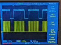
But the pulses on T (ch2) (when zoomed into when IC2P12 is high) is at 2.66KHz.
PXL_20240329_030618629.MP.jpg

This is at 1.0ms/div.

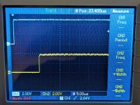
The other tests are done at 5us/div when T is high. Which may explain why it looks inverted?
 
Just some thoughts...

When T is high, the "random" signals at the outputs of IC47 and IC55 latches are only random under the assumption that the video RAM contains random data. This will not be the case when the video RAM has been initialized before (e.g. during a RAM test).

Concerning the relationship between the inputs and outputs of IC46, you probably should check the related inputs and outputs in parallel in order to check whether inputs and outputs really differ during IC46-15 being low. Only in that case the chip is probably faulty.

It seems that the signal going into IC46-15 (which enables the outputs of IC46) is going low after a certain delay after T going high. So it is made sure that the address and video data are stable on the bus when IC46 is being triggered at IC46-15.

This, however, also means that everything happening at the inputs of IC46 while IC46-15 is high will *not* go to the outputs. From measurement 28, it seems that during T high phase there is no "random" data anyway (possibly because the video RAM is all zero), so you might see "random" data at the inputs of IC46 during T being low, but not at the ouputs of IC46 since the output is always disabled (=low) during T going high, plus some delay.

I guess the interesting question is whether the actual data from the video RAM (check or initialize with your monitor program) is identical to what is provided by the 74LS04 input buffers (IC64 and IC72) and 74175 latches (IC47 and IC55) and IC46 finally provides to the video board during IC46-15 being low for every single data bit. Not that easy to measure when you have just two channels, but you might use any of the IC46 outputs going high as a trigger (assuming the video memory is not zero'ed). IC46 outputs will be continuously low in the phase where they are not of any interest for the video board.

(By the way, I am always confusing 74157 and 74175 when installing the chips...)

*** small correction: you might see "random" data at the inputs of IC46 during T being low, but not at the ouputs of IC46 since the output is always disabled (=low) __until__ T going high, plus some delay.
 
Be aware that the test point 'T' is a combination of two pulse trains. Looking at 'T' with different timebases will 'bring into view' different aspects of the signal.

This is partially the problem of fault finding an issue. We have to return to the correct initial conditions (oscilloscope configuration) to restart the testing.

For a 512 byte screen memory located at address 0000 this will extend to address 01FF. This does encompass the RDOS stack and workspace, so the RAM here should not be purely FFh or 00h.

However, if we need to guarantee some data bytes are here are not 00h, you could always load some into here - just be careful not to corrupt RDOS!

EDIT: The key initial condition is in step 23 where it is requested to set the timebase to 5 us/div with a positive trigger slope to ensure the 'high' part of test point 'T' fills the screen. I would expect to be able to see the falling part of 'T' at the right-hand edge of the scilloscope screen (just to make sure we don't miss anything when 'T' is high).

Dave
 
Last edited:
Back
Top