• Please review our updated Terms and Rules here

Fixing Five Festive 5150 Boards over the Holidays (BOARD #3 Thread)

It produced a file very similar to yours, with a few differences. Unsure if functionality is equivalent, guess I'll have to burn it to an eprom and see if the address bus is toggling heheh.
I'm puzzled by the E9. I just now recompiled TEST5065.ASM, and the E9 is not in the resulting BIN file. I will look into that.

But I certainly plan to do that modification (very shortly), creating TEST5066. Included in the ZIP file for TEST5066 will be logic analyser captures of the address bus, and the memory data bus.
I created TEST5066, which is now at [here]. A page refresh in your browser may be required. I have yet to bring out my logic analyser to confirm the BIN file, and produce logic analyser captures.

Note that TEST5066 refers to the address bus and the external address bus, but omits the memory data bus. That is primarily because the memory data bus has two addresses on it (a row address then a column address) for every address presented to the address bus.
 
I used to have many 51xx motherboards, now down to about 8. These are boards that I have had for many years, and are stored well. I make sure they get periodic 'exercise'. Sometimes I bring out a motherboard (that was put away in working state), and discover that it no longer works. Of course, I do not know if the faulty component failed at application of power, or failed during storage.
Great example photos. I think that the damage is already done in many cases due to the years of storage by previous owners who kept them in moist environments like a basement or shed. This grows oxidation on the components which can lead to failure in certain parts. Afterwards the boards are taken good care of but the damage is already there. I think here you can see which parts are of better manufacturing quality because the package is more sealed and still functional. Though of course no component is made to be stored in extremely moist circumstances.

Some components like especially DRAMs suffer from internal ageing due to the chip dye, certain materials on the silicon are not durable because they age faster. I have heard this before. Just time alone can render certain chips faulty.

I am thinking I should find some treatment spray to see what it can do to remove the oxidation layers on my 5170 mainboard, perhaps doing some kind of treatment can preserve the ICs more and make the mainboard look better in the process.

If only some modern chip manufacturer could run a few batches of new DRAMs using modern technology for the silicon, package and pins which will last much longer. I am sure many of such chips can find some buyers in today's retro enthousiast market. Even replacing working chips to increase the reliability of these old mainboards could be a reason to want to buy a supply of these.
 
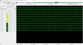
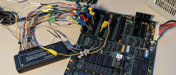
I setup logic probes on an ISA slot. Double checked the eprom, wiring and continuity, did a capture. With TEST5066 running I don't see 55555 or AAAAA. Closest I get is "565E". There's also an "FEh" every other state, which I don't see on your capture. I notice there's no activity on A18 & A19 which I verified with the logic probe. Odd this.

1703973528467.png
 

Attachments

  • 5150-TEST5066-Addr-on-ISA-bus.CSV.txt
    130.5 KB · Views: 1
I setup logic probes on an ISA slot. Double checked the eprom, wiring and continuity, did a capture. With TEST5066 running I don't see 55555 or AAAAA. Closest I get is "565E". There's also an "FEh" every other state, which I don't see on your capture.
In my capture, between the 55555's and AAAAA's are U33 ROM addresses (i.e. addresses of the executing code).

1704001581927.png

I notice there's no activity on A18 & A19 which I verified with the logic probe. Odd this.
And both always LOW.
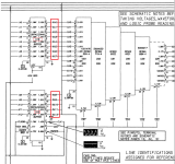
If instead, both were always HIGH, then per the diagram at [here], RDR would still execute.
However, maybe they are LOW on the address bus, but HIGH on the external address bus.
 
Happy new year! I performed a capture of the external data bus on U16 & U15, XA0-XA12 running TEST5066. For some reason I'm still not seeing the 10101 patterns. Strange, I thought we would see something here.

1704493456675.png
1704493261793.png
 

Attachments

  • 5150-TEST5066-Addr-on-EXT-bus.CSV.txt
    81.9 KB · Views: 0
However, maybe they are LOW on the address bus, but HIGH on the external address bus.
Doh. A18 and A19 don't flow through to the external address bus.

I performed a capture of the external data bus on U16 & U15, XA0-XA12 running TEST5066. For some reason I'm still not seeing the 10101 patterns. Strange, I thought we would see something here.
The external data bus derives from the lowest 13 bits of the address bus. If you are not seeing the __1010__ patterns on the lowest 13 bits of the address bus, then the __1010__ patterns are not expected on the external address bus.

Looking at your capture of the address bus (put aside the external address bus), I see that A8 is always low. Refer to the diagram at [here]. Is the A8 pin on the CPU also always low ?
 
I'm getting mixed results on A8. If I keep the logic probe on there and power-cycle the board, about 1 out of every 5-10 boots, A8 is not pulsing and the other's it is. When it's not pulsing, A8 on the cpu isn't either and the status bits are all high.

Here's a capture with A8 pulsing:
1704502943863.png
 

Attachments

  • 5150-TEST5066-2-Addr-on-EXT-bus.CSV.txt
    82.4 KB · Views: 0
I'm having a hard time understanding how RDR will run on this board, and yet my captures make no sense. I wonder if there's something wrong with my logicport device. Maybe I'll try to verify it's accuracy with an Arduino test program.
 
Post #36: Version 2022-12-12 of RDR executes fully. Of note is that 2022-12-12 does not do an address test of the RAM.

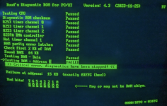
Post #46: Version 4.3 of RDR fails during the address test of the RAM.

'RAM bank 0 only' operation. Known good RAM chips in bank 0.

Per [here], to execute, RDR only requires some of the address bus to be functional.

Post #64: Using TEST5066, a logic analyser capture of the address bus (not the external address bus) is not even showing motherboard addresses that correspond to the U33 ROM socket.

Regarding that last comment. We know that RDR executes. So surely, some of the addresses in your address bus capture should be motherboard addresses that correspond to the U33 ROM socket, like what I showed in post #65.

LogicPort analyser

Connecting up some of the ground wires ?

Are you really confident that you are using the correct wires on your LogicPort analyser? I have been caught out quite a few times. Sometimes, on an unconnected wire, I see a signal that duplicates a signal on one of the connected wires.
Sometimes, to make sure I am using the right wire:
1. I ground the wire. As expected, I see the signal always LOW.
2. I then connect the wire to +5V. As expected, I then see the signal always HIGH.
 
I'm having a hard time understanding how RDR will run on this board,
Going back over the years, we had some cases where people were reporting that the Supersoft/Landmark Diagnostic ROM (SLDR) was fully passing, but the known-good IBM BIOS ROM wasn't displaying anything, nor beeping.
In two cases that I recall, it turned out that:
- The POST in the IBM BIOS ROM looks for certain kinds of RAM addressing problems, and if it finds such, halts without any form of indication (visual or audible).
- The SDLR and early versions of RDR do not look for RAM addressing problems.

And per [here], to execute, RDR (and SLDR) only requires some of the address bus be functional.
 
Good review and reminders there. This logic analyzer is second-hand, so to remove doubt I wrote a small Arduino program to simulate an 8 bit bus counting from 0-255. I tested yellow and green wire groups and they're good. I'll test the other two groups when I get a few more grabbers.

Connecting up some of the ground wires ?
Yes making sure of that. I wonder if some of the legs are dirty enough to prevent good contact, I'll check with a multimeter.

Are you really confident that you are using the correct wires on your LogicPort analyser? I have been caught out quite a few times.
Totally agreed, I've done the same! I have the four groups of wires separated with wire ties, and my grabbers are somewhat color coded which helps. On that last capture I double checked and couldn't find a conflict.

p.s. I borrowed some of your format for the readme in the zip :)
 

Attachments

  • LogicTest.zip
    77.5 KB · Views: 1
On this motherboard, has the CPU been swapped out for a known-good one ?
Good question. I swapped in the cpu from my working 5150 and got the same results with RDR.

Hold on though, I may have had a pin on the eprom adapter bent during the 5066 test. I have to do another capture to see if that was the issue.

1704580643880.png
 
I wonder how much effort it would be to add a beep to these diagnostic tests. I realize this is assembly so nothing is easy though heheh.
 
Hold on though, I may have had a pin on the eprom adapter bent during the 5066 test. I have to do another capture to see if that was the issue.
And you could do a capture of the address bus when RDR is seen executing on-screen, expecting the capture to show motherboard addresses that correspond to the U33 ROM socket.
 
I wonder how much effort it would be to add a beep to these diagnostic tests. I realize this is assembly so nothing is easy though heheh.
The assembly code is straightforward.

These various TEST5xxx tests are run on a faulty motherboard, and one is never sure how much of the motherboard is not functional. Therefore, if there is to be some indication that the TEST5xxx code is executing, it would be done using the minimum amount of hardware possible. On the IBM 5150, that would be like what TEST5083 does, toggling the voltage on pins of the 8255 chip at roughly a particular frequency, a frequency that a user can easily see with a multimeter (and hear the motherboard's relay click).

In the case of TEST5066, it is being executed because of a possible problem on the address bus involving one or more bits. Even now, the executing code being less than 30 bytes long, there will be some particular bad-address-bit motherboards where TEST5066 won't run at all (because of the particular bad address bit/s). Adding extra code makes the situation worse - more motherboards won't be able to execute TEST5066. For TEST5066, adding the TEST5083 code to it would triple the code in it. It's just undesirable. So, it's not something that I would put into the public TEST5066. But if you like, I will create a custom TEST5066 and DM that to you.
 
And you could do a capture of the address bus when RDR is seen executing on-screen, expecting the capture to show motherboard addresses that correspond to the U33 ROM socket.
True, as in [here]

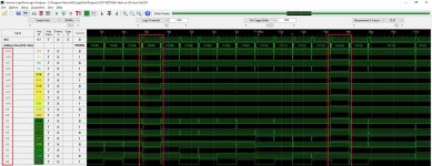
Ok, I reseated test 5066 and ran a capture with only A0-A7 & ALE. I can now see 55 & AA! Finally getting some traction on this.

A0-A7-Test-5066.JPG

Zooming out (something I wasn't doing before) I can see the execution pattern better, where "55" is always the 11'th address in the repeating pattern, and "AA" is always the second to last:

A0-A7-Test-5066-Pattern.JPG

I'll widen the capture now.
 
Ok address bus A0-A19 at the ISA slot reads good running test 5066. Moving on to the external bus now...

A0-A7-Test-5066-Full.JPG

1704590236475.png
 
Last edited:
I found 5's and A's on the External Address Bus XA0-XA12 as well.

A0-A7-Test-5066-EXT.JPG
index.php
 
Back
Top