• Please review our updated Terms and Rules here

M8189 bootstrap error LED's D1 and D4 on

@cmao, you should make a diagram and provide measurements to make clear for everybody what you measure.
I would measure +5V in three places:
- At the ATX power connector
- At the cable sending power to your backplane
- At the rear of the backplane
- On one board (on one IC)

For a classical LSI-11 it would be something like this:
View attachment 1257105
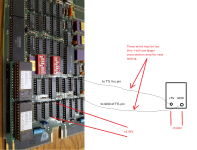
I remove M8189 from backplane and test the voltage drop. Attached is the setup

1683581262384.png
 
Hold on.

Are you just connecting a 5V supply across a chip and measuring the voltage across another chip?

This is not representative at all if you are.

Dave
 
@cmao, you should make a diagram and provide measurements to make clear for everybody what you measure.
I would measure +5V in three places:
- At the ATX power connector
- At the cable sending power to your backplane
- At the rear of the backplane
- On one board (on one IC)

For a classical LSI-11 it would be something like this:
View attachment 1257105
I suspect the ATX PSU may not work as specific ratings. I am acquiring a good quality ATX to see if the problem can be solved.
 
Hold on.

Are you just connecting a 5V supply across a chip and measuring the voltage across another chip?

This is not representative at all if you are.

Dave
No. there is a terminal panel with voltage conditioning in between. M8189 is safe.
 
I am asking how you have connected the power supply to the M8189 if you are not using the QBUS backplane.

Dave
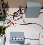
The way the power connected to backplane is exact the same design per https://avitech.com.au/?page_id=1657. A high quality ATX will be delivered this week. I am hoping it will resolve the issue. I strongly suspect that the PSU I am using did not maintain steady voltage under loading. This PSU is very old. The capacitors or other components on PSU board could have been out of function.
1683638004723.png
 
Just out of interest, how many separate wires (of what gauge) connected the original ATX supply to the PC, and how many have been connected between the ATX supply and the PDP?

How are the cables terminated on the PDP backplane?

The voltage drop across a cable is directly proportional to the current flowing and cable resistance. The cable resistance increases with length and decreases with cross-sectional area (CSA). The CSA is proportional to the number of individual strands of wire, and the area of each strand.

In addition, all this can be undone by not terminating the cable correctly...

Dave
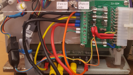
Dave, I remove the fuse and bridge +5V with 2 large cross-sectional wires in parallel. I also replace +5V and GROUND wires with large cross-sectional wires along the path to the backplane. There is NO voltage drop !. I think the fuse and thin wires in series cause significant voltage drop.
1683730770294.png
 
Thin wires (small Cross-sectional area) do cause large volt drops (especially with large currents). That is why I stated it :)!

I am not too sure that the fuse would be to blame though...

Glad you have now significantly reduced the environmental heating...

Dave
 
Thin wires (small Cross-sectional area) do cause large volt drops (especially with large currents). That is why I stated it :)!

I am not too sure that the fuse would be to blame though...

Glad you have now significantly reduced the environmental heating...

Dave
there is 0.35V voltage drop between two ends of fuse and the fuse dissipates lots of heat. It is so hot !! Thin wires contribute about 0.4V drop.
 
>>> there is 0.35V voltage drop between two ends of fuse and the fuse dissipates lots of heat.

I suppose that is the basis of how the fuse works... It gets hot based upon the current flow and eventually melts the metal once it gets hot enough. In order for the fuse wire to get hot, it has to have some resistance.

Good work at documenting the individual volt drops for other people in the future...

Dave
 
My M8189 can work with the memory board M8067 that is configured to 18-bit mode. 9 steps of memory tests pass. However, M8189 still cannot boot the RX02 emulator. I am doing research on RX02 controller, M8029. If anyone has experiences using M8029. Please share your experiences. Thank you in advance.
 
This may be a dumb question, but are you sure your board has the boot code for this device? If you try to boot what does it do?
 
My M8189 can work with the memory board M8067 that is configured to 18-bit mode. 9 steps of memory tests pass. However, M8189 still cannot boot the RX02 emulator. I am doing research on RX02 controller, M8029. If anyone has experiences using M8029. Please share your experiences. Thank you in advance.
Does your RXV21 respond at the standard CSR address of 777170?

You might want to check the bus address config jumpers if it does not.

Have you seen this document? https://github.com/AK6DN/rx02_emula...012-PS-002_RX01_RX02_Pocket_Service_Guide.pdf

It has some sections on that card that may provide useful background info.
 
Last edited:
This may be a dumb question, but are you sure your board has the boot code for this device? If you try to boot what does it do?
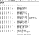
Can someone confirm the boot setting S1 on M8189 with KDF11B-BJ ROM ? Below is for KDF11B-BE. I set S1 on M8189 per Table 2-14 but nothing happens.

1684069983305.png
 
Last edited:
Last edited:
Does your RXV21 respond at the standard CSR address of 777170?

You might want to check the bus address config jumpers if it does not.

Have you seen this document? https://github.com/AK6DN/rx02_emula...012-PS-002_RX01_RX02_Pocket_Service_Guide.pdf

It has some sections on that card that may provide useful background info.
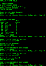
Here is the M8189 response by toggling "RESTART". Please note that the message "Boot Switch (S1) Invalid" indicates the M8029, RX02 controller, is not found by M8189. I am not sure if I set the wrong value for S1. I also note that the RX02 emulator response (see the second attached picture) immediately after the toggling. Does the emulator response too soon?

1684073814947.png


1684073884192.png
 
Back
Top