• Please review our updated Terms and Rules here

M8189 bootstrap error LED's D1 and D4 on

So the error is that the CPU is not happy with the controller itself.

Have you tried using ODT to open the I/O address for the controller and see if it is actually responding or not?

In the posts above, Don identified the 18-bit address and you responded with the 16-bit address. On an 18-bit system you have to enter the correct 18-bit address for the controller - otherwise ODT returns memory...

Dave
How do I know I response with 16-address ? How do I open controller using ODT ?
 
Enter the 18-bit base I/O address of the controller (in octal) at the ODT '@' prompt (e.g. '777170') and then press '/'. If the controller doesn't exist it should display a '?' mark and return to the '@' prompt. If it does exist, it should display the 16-bit value of the control and status register. You can ignore the actual value - all we are interested in is "does the controller respond". Press the <RETURN> key to finish.

Code:
@777170/

Also, judging by your printout, you have the Map command available to you. I have tried running Map to see how much memory you have and what devices are present in the I/O page?

Dave
 
Yes, Map should show you what memory it sees and which devices it sees also. Very handy.
 
Enter the 18-bit base I/O address of the controller (in octal) at the ODT '@' prompt (e.g. '777170') and then press '/'. If the controller doesn't exist it should display a '?' mark and return to the '@' prompt. If it does exist, it should display the 16-bit value of the control and status register. You can ignore the actual value - all we are interested in is "does the controller respond". Press the <RETURN> key to finish.

Code:
@777170/

Also, judging by your printout, you have the Map command available to you. I have tried running Map to see how much memory you have and what devices are present in the I/O page?

Dave
Dave,

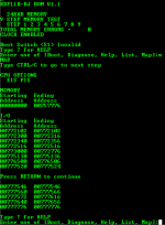
The size of memory and I/O address are listed below. The actual memory size is 253950 (757776 octal) x 18-bit. So how can I select one proper I/O address for my M8029 ?

1684100633181.png

1684100985200.png
 
The expected address for the controller is 777170, and it doesn't appear in the I/O map, so either the M8029 is configured wrongly, or it is dead. This is inevitably why it doesn't boot.

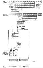
You have posted the links for the M8029, but which links are actually present on your M8029?

Dave
 
The expected address for the controller is 777170, and it doesn't appear in the I/O map, so either the M8029 is configured wrongly, or it is dead. This is inevitably why it doesn't boot.

You have posted the links for the M8029, but which links are actually present on your M8029?

Dave
If "1" = the jumper is removed and "0" = the jumper is installed, then my M8029 is currently configured NOT for 777170 or 777200. It seems current mapped address is 0000110000 = 60 (octal). correct ?

By the way, I got

@777170/?
@177170/0000

1684102330538.png
 
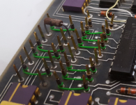
By link I think Dave meant to inquire which wire links/jumpers are installed, not an internet URL link...

Your picture helps somewhat, but the oblique angle of it makes 100% determination a bit hard to see, esp. for the wires near the top...
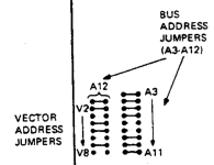
Ok. my M8029 is configured as below. It seems it is neither 777170 nor 777200. correct ?

1684105058988.png
 
That part of the drawing (removed="1", installed="0" seems backward for the CSR. From looking at the picture your board seems to be strapped correctly.
 
Hard to say, the green jumpers from A11 to A4 look correct (3xIN, 2xOUT, 3xIN). But the jumper on A3 (a white wire) is only partially visible.
If the white wire is not a functional jumper, the address would appear at 777160 instead of 777170.
But neither of 77716X or 77717X appear in the MAP output ...
 
The address range in the MAP of 775130..775136 is the right block size, and is correct except for two bits that are 0 instead of 1 (bits 10,5).
I don't recognize 775130 but maybe it is a valid I/O address for something IDK.

... according to a DEC peripherals manual 775000...775176 is reserved for DM11 #1 thru #15 devices... which I doubt very much you have...

... you might want to check the resistance of some of those jumpers from pin to pin. Maybe a couple of them have opened or gone high resistance.
 
Last edited:
>>> By link I think Dave meant to inquire which wire links/jumpers are installed, not an internet URL link...

Thanks for the clarification Don. Yes I did.

I also agree that the documentation manual appears to be incorrect regarding the link insert/removed state. I also believe the correct state to be is INSTALLED=1, REMOVED=0 for the address. Let's ignore the vector for now. This then causes the manual text to align with the default configuration (as also shown within the manual).

This gives us a default address of 1111001111XXX (note the X's because these three address lines are not used to decode the base address of the card, but to select internal registers on the card). However, these address lines have to be taken into account when converting from the link settings to the correct base address for the card. Also, the card 'lives' in the I/O space, so you need to pad the above code to 16 bits (or 18 bits) by pre-pending 1's. As a 16-bit I/O address you would have 1111111001111XXX which (when converted to octal) is 177170 (substituting '0' for X). As an 18-bit I/O address you would have 111111111001111XXX which (when converted to octal) is 777170 (again,substituting '0' for X).

As Don says, we can't see where the white wire wrap is connected to, so we don't really know whether A3 is correct or not.

Code:
By the way, I got

@777170/?
@177170/0000

This is correct. 177170 (in an 18 bit machine - with a 16-bit address) addresses the RAM. 777170 (in an 18-bit machine) is addressing a non-existent I/O device.

Let us assume that your controller is working (but we don't know at what I/O address it is appearing as). A simple way to identify it is to physically remove it from the backplane and perform another MAP. It should not now appear in the map of I/O addresses. If you get exactly the same response from the map command without the card being installed as you did with the card being installed - it is likely to be dead.

It should also not depend upon the specific QBUS slot that the card is physically plugged into (providing it is really a QBUS AB slot of course). This correct placement is only of significance for interrupt and DMA devices.

Hope this makes sense to you?

Dave
Dave,

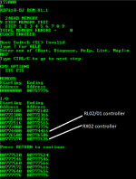
It is interesting. I inserted RL02/01 controller (M8061) to slot 3 and RX02 controller (M8029) to slot 5 and now I can see the I/O map for both controllers. Can someone explain why I can see both the controller listed in the I/O map?
1684160389827.png
1684160201626.png

1684160501267.png

1684158555264.png

However, when I try to boot RX02 emulator, I got ERROR 15 that indicated the controller is dead which is we expect to see.

1684158748111.png

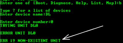
and I got ERROR 19 while booting RL02. This makes sense because there is no hard drive connected to controller. The RL02 controller could be a good one.

1684159006320.png

It seems the RX02 controller is dead and RL02/01 controller is functional.
 

Attachments

  • 1684160188221.png
    1684160188221.png
    1.9 KB · Views: 1
Last edited:
ODT assumes you are giving it a physical address. Unspecified leading bits are assumed to be 0. If you give it an address from 160000 to 170000, intending to access something in the I/O page, and you're in an 18 or 22 bit environment, you're not going to get the results you want.

In short, in an 18 bit environment, the I/O page goes from 760000 to 777777. In a 22 bit environment it goes from 17760000 to 77777777.

Take a look at page 3 in the document linked here:


In an 18 bit or 22 bit machine, the MMU will do the mapping for a running program. If you're dealing with ODT, you have to remember to do the mapping for yourself.

And I frequently don't.
 
This is an interesting turn of events!

Not sere why that occurs...

To save any confusion (since we have had a number of historical posts - and I still don't know exactly what backplane you have) can we have an EXACT description of your backplane and which cards are installed in which slots (especially the A/B, C/D and E/F parts of the slots). Both with the RL controller and without.

I was just looking at the schematics for the M8029 and trying to find out whether it needs a device connected to it or not to 'work'.

Dave
 
So was the M8029 in slot 5 before you added the RL02? Or did you move it? Could it be that the vector is still off from what it should be? It appears to be correct, but what is that "resistor like thing" pictured for V2 of the vector?
 
Yes, I wondered what that thing was also...

We also didn't get an answer regarding the 'flapping around' white wire either...

An incorrect vector may stop it from booting - but it shouldn't stop the controller from responding to I/O requests - unless these requests go through to the electronics in the RX01/02 drive and back? I am still hunting through the documentation to find an answer to this question...

Perhaps someone with more knowledge than me can answer this question...

Dave
 
This is an interesting turn of events!

Not sere why that occurs...

To save any confusion (since we have had a number of historical posts - and I still don't know exactly what backplane you have) can we have an EXACT description of your backplane and which cards are installed in which slots (especially the A/B, C/D and E/F parts of the slots). Both with the RL controller and without.

I was just looking at the schematics for the M8029 and trying to find out whether it needs a device connected to it or not to 'work'.

Dave
I have no details about my backplane. No model number printed on PCB. Here are the setup

New setup:
Slot 1: M8189 (ABCD)
Slot 2: M8067 (ABCD)
Slot 3: empty
Slot 4: M8061 (ABCD)
Slot 5: empty
Slot 6: M8029 (AB)

original setup
Slot 1: M8189 (ABCD)
Slot 2: M8067 (ABCD)
Slot 3: M8029 (AB)
 
Back
Top