• Please review our updated Terms and Rules here

Neglected PET needing some love

Have you made the composite adapter with the three NOR gates ?
Hugo,
No, that is not necessary with the RGB board. You simply use the three buffered TTL video signals available at the PET User Port. On my RGB to HDMI board there is a convenient 9 pin CGA input connector. You make a cable and hook up the PET video data line to the green video input of the CGA, and the Vertical and Horizontal Drive signals into the corresponding CGA H and V pins. It has to be all TTL signals. The board uses a Raspberry Pi and a programmable chip to do all the processing.
 
Well I tried playing with every conceivable setting in the RGB2HDMI and couldn't get it dialed in any better than in the video I posted. I noticed that the text sometimes says "ready." and sometimes is garbled like in the video.
Divarin,
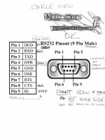
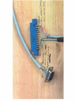
You have two issues. The PET main board is not working well yet and the setup or cabling to the RGB2HDMI may not be right. I was initially confused with the info on the net about the CGA connector as to what view it presented, the PC end view or the cable end view. Attached is some info to double check your wiring.
-dave_m

RGB_HDMI2.jpegRGB_HDMI1.jpeg
 
Dave,

Can you provide a link to the adapter you are using? It sounds interesting...

Dave
daver,
Yes it is quite a gadget and seems solid. There are different versions/makers of this type of board, but this one came with a convenient input connector.
It says '6 bit" meaning that it can handle six TTL inputs like R,G, B and sync signals.

https://texelec.com/product/rgbtohdmi-ttl/
This particular gadget does not handle analog input such as the VGA interface. Digital signals only like MDA, CGA and EGA type interfaces. The PET needs custom configuration settings (performed in the configuration menu of the gadget). Chuck Hutchins has created profiles for PET users of both 9" and 12" screens. See his youtube video on the subject. The files would need to be added to the existing SD card on the gadget board. In my case I put his parameters into an existing profile (Acorn Electronics) and saved that configuration. I had to play with his settings a little to get my cheap monitor to sync. Any HDMI monitor should work connected to the output of the gadget.
 
Last edited:
Hugo,
No, that is not necessary with the RGB board. You simply use the three buffered TTL video signals available at the PET User Port. On my RGB to HDMI board there is a convenient 9 pin CGA input connector. You make a cable and hook up the PET video data line to the green video input of the CGA, and the Vertical and Horizontal Drive signals into the corresponding CGA H and V pins. It has to be all TTL signals. The board uses a Raspberry Pi and a programmable chip to do all the processing.
Interesting.

Does that work for both the non- CRTC PETs with 9" VDU's and CRTC PETs with 12" VDU's ?

It is interesting that the polarity of the H drive pulse is different (At least what is fed to the VDU), but maybe it is the same at the user port though in the two machines or is that selected by the raspberry pi program ?
 
It is interesting that the polarity of the H drive pulse is different (At least what is fed to the VDU), but maybe it is the same at the user port though in the two machines or is that selected by the raspberry pi program ?
No, the syncs to the user port are the same polarity as the signals to the PET video card. In the RGB board, the sync parameters are selectable. You have a choice of positive or negative polarity on each sync as well as composite sync. See message #54 for a shot of the geometry menu. Look down to the parameter 'Sync Type'. You will see "-H-V" for the 8032 PET.
The board designer seems to have thought of everything.

Note: Hey, we may have a clue for our OP.
I just played with the polarity settings on the RGB board and if I selected composite, the screen started scrolling vertically. I wonder if he is using the right profile for the PET?
 
Last edited:
Note: Hey, we may have a clue for our OP.
I just played with the polarity settings on the RGB board and if I selected composite, the screen started scrolling vertically. I wonder if he is using the right profile for the PET?
Yes, that is handy. And for the non CRTC PETs with the 9" VDU's, it would have to be selected for +H-V, I would guess.
 
Divarin,
You have two issues. The PET main board is not working well yet and the setup or cabling to the RGB2HDMI may not be right. I was initially confused with the info on the net about the CGA connector as to what view it presented, the PC end view or the cable end view. Attached is some info to double check your wiring.
-dave_m

View attachment 1246881View attachment 1246882
this is very helpful thanks. I'm going to compare this with my wiring diagram and the cable I made and get back to you on this.
 
It looks like my wiring is the same as yours. At first it looked backwards but that's because it's a female connector. The reason I'm using a female connector is because there's already a 9pin cable running from the rgb2hdmi and the pi is a little inaccessible whereas the cable connected to it (which I normally used on a c128) is right there on the desk where the pet would be set up. So I opted for a female connector to plug into that.

I'm using one of these: https://www.amazon.com/dp/B073RGGDKH
The pin numbers are labeled where you attach the wire and for testing I did confirm that the signal does go all the way from the PET motherboard's edge connector to the hole in the 9 pin connector (not just where the wire plugs in but where the pins of the male connector goes in). So for me the pin numbers are mirrored from that of the male connector but the numbering is consistent. In other words pin 4 (for example) is top row 4th from the right instead of 4th from the left.

I was working on the same video frame as you (the one you posted) and it looked like an additional ground was connected between pin 24 (on the PET) to the shielding around the 9 pin connector. I tried connecting that as well but that didn't help (I didn't really expect it would)
 
If your wiring is correct and you have played with the parameters with no effect, I would think your RGB board is broken. But does the C128 interface work? If so that is very confusing. There is a profile for the C128. Did it work right off the bat?
 
If your wiring is correct and you have played with the parameters with no effect, I would think your RGB board is broken. But does the C128 interface work? If so that is very confusing. There is a profile for the C128. Did it work right off the bat?
Yeah the RGB board works fine I use it on my 128 almost every day.
 
Playing around with it some more today it's behaving a bit differently. It seems to be cycling through random characters on the screen. then after letting it warm up a while it was just columns of 3's, flashing (see video)
After a while I power-cycled it and I see "ready.reready.reready.reready..." with the R's in "ready" flashing I'm assuming it's saying "reready" because it's writing over another "ready", dunno.

I'm getting this "ready.reready..." behavior consistently now through multiple power-cycling.

It does seem like the RGB2HDMI is finally working I don't know if the pet was not giving a proper sync before or maybe it was just so garbled I couldn't tell if it was syncing or not.

Video: (still processing by youtube)
 
It wasn't really clear to me whether you managed to work out the approximate frequencies of the H-Drive and V-Drive signals when you were trying to scope them - if not, do you have any straightforward method to measure the frequencies of those signals? For example a lot of Multimeters have a 'Hz' range on them now which can be used to measure frequency up to one or two MHz. Your difficulties may be partly because the frequencies are out of range due to some problem further back in the PET.

It would be good if you could rule this out by measuring the frequency of the signals coming out on V-Drive and H-Drive with a frequency meter or the frequency measurement feature on a multimeter. Apologies if you already did this and I missed it.
 
Last edited:
It wasn't really clear to me whether you managed to work out the approximate frequencies of the H-Drive and V-Drive signals when you were trying to scope them - if not, do you have any straightforward method to measure the frequencies of those signals? For exampel a lot of Multimeters have a 'Hz' range on them now which can be used to measure frequency up to one or two MHz. Your difficulties may be partly because the frequencies are out of range due to some problem further back in the PET.

It would be good if you could rule this out by measuring the frequency of the signals coming out on V-Drive and H-Drive with a frequency meter or the frequency measurement feature on a multimeter. Apologies if you already did this and I missed it.
I wasn't able to determine the frequencies of the H and V drives. I have 3 multimeters but they're all cheapos and don't have that functionality.

There's definitely a temperature (or possibly capacitance) component here. I can repeat the behavior in the video above (except with "ready.reready.reready..." instead of "3"). If it's cold I see random mismash of pixels but as it warms up that fuzz (I'll call it that for now for lack of a better word) clears up and I see clear characters. But... even when the characters are clear it's still just repeating "ready.reready.reready..." forever.

I think when I get more time I'll have to start poking around the board looking at voltages and maybe desoldering/testing the electrolytic caps.
 
It wasn't really clear to me whether you managed to work out the approximate frequencies of the H-Drive and V-Drive signals when you were trying to scope them
Good catch Sirius. When I checked his scope photo early on, I thought all was fine when I saw a 20 KHz waveform. This is correct for the Horizontal Drive. But looking at it again, our OP says he was checking the Vertical Drive signal which should be 60 Hz. He should recheck these timing signals before worrying about anything else. He should use channel 1 and trigger on CH1.
 
Good catch Sirius. When I checked his scope photo early on, I thought all was fine when I saw a 20 KHz waveform. This is correct for the Horizontal Drive. But looking at it again, our OP says he was checking the Vertical Drive signal which should be 60 Hz. He should recheck these timing signals before worrying about anything else. He should use channel 1 and trigger on CH1.
This scope doesn't have any triggers. I have been looking around for some better test equipment. Maybe one of those oscilloscopes that connect to a PC.
 
Back
Top