• Please review our updated Terms and Rules here

Neglected PET needing some love

The controls are on the right hand side (in the green or blue coloured area). I am green/blue colour blind!

Dave
 
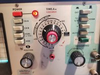
I think what Dave means is that your scope DOES have a trigger (because they all do) but maybe you haven't got as far as knowing how to use that part of it. Looking at the photo of your scope's front panel in your post #36 I can see that the controls in the blue shaded area, upper right on the panel (but unfortunately only half visible in the picture) are the trigger controls. If you can take a well lit, well focused photo of the whole front panel of the scope we may be able to give you a crash course in using the trigger facility. The scope model is 'Hickok 517', if anyone can dig up an online user manual.

Edit: Crossed with Divarin and daver2
 
Last edited:
Went looking for a manual online, no luck but I did find a nice picture of the trigger controls posted by none other than Divarin over on AtariAge a couple of years ago. It's also worth pointing out that for any measurements made with the scope to be meaningful, all of the red knobs need to be turned fully clockwise to the 'Cal' position (where there is probably a click-stop) and left in that position.


Hickok_517_Trigger_controls.jpg
 
ah I see. actually are you sure that photo wasn't posted by me? it has the same scuff marks in the same places.

ok so... how do I use the triggering?
 
Yes, it was posted by you :) "None other than Divarin".

It's a little bit late now here in the UK but I'm sure the guys over on your side can explain how to use the trigger - if not, we can look at that again tomorrow.
 
In the trigger section, have all the buttons clicked up/out and use the trigger level knob to get a consistent trigger point.

For the vertical drive signal use the time base at 5 mS as signal has a period of 16.66 mS and for the horizontal drive signal use 20 uS as signal has a period of 50 uS.
Use Channel A.
 
For each waveform of interest you need to try to get two pulses on the screen at the same time so you can count the number of squares between their leading edges. Bear in mind what was mentioned earlier about the red CAL knobs, they all need to be fully clockwise otherwise any measurements made will be meaningless.
 
Last edited:
Alright so I set it to 5 mS and I tried probing the vertical. I see the signal on the scope, then I pop all of the button in the trigger area out, but nothing shows on the scope. I very slowly moved the level knob from one extreme to the other. The only thing I can get is a very brief blip as I'm turning the knob and then only if I'm turning it somewhat quickly. If I turn slower and try to zero in on that spot then I get nothing.

I also double checked that all of the red CAL knobs are turned all the way to the clockwise position.
 
If you press the Auto / Norm switch back in, do you get the trace back? If so, leave it in that position.

Try putting your probe tip in the 'Probe Cal' socket - do you get a waveform on the screen then, and if you do, are you able to make it lock up nice and steady by varying the Trigger Level rotary control? There should be a FROM and TO point on the travel of the control where the waveform on the screen will hold rock steady - outside of that range of adjustment the trace will lose lock.
 
if I switch it to auto the signal shows up.

with the probe in the cal socket i get a waveform but the behavior of the level knob is the same.

what i just realized is the blip only shows up while I'm turning the knob down as I pass a certain point. if I'm turning it up nothing happens.
 
And when you say the signal shows up with AUTO selected, what does it look like? Is it travelling from left to right or from right to left, or does it hold steady on the screen?

Try pressing the middle (+ / -) switch in and repeating your Trigger Level slow turning experiment above, do you now get the 'blip' when you are turning the knob up, rather than when you are turning it down?

Travelling.

If a picture is worth a thousand words then a video is worth a million:

 
It certainly doesn't seem as though your trigger circuit is working properly. Excluding the possibility of a real electronic fault for the moment, the most common reason I have seen for a non-working trigger on old analogue scopes is simply dirty switches, especially those closely associated with the trigger functions such as

'INT/EXT',

'+/-'

'TV V-H/Norm'

...and so on. If you just 'exercise' each of those switches (vigorously operate them back and forth) for a minute or so each you may well find that gets the trigger facility working by scraping the tarnish and old grease off the switch contacts.

Whether you want to try to do anything about this is up to you, you could probably buy a multimeter with a 'Hz' range for about $10-$20 over there just to resolve the V-Drive and H-Drive frequency question but a fully working scope is ultimately much more useful than a half working one.
 
That scope seems flaky.
Use a voltmeter and measure the horizontal drive. The DC average should be around 2.5 V.
Unfortunately the voltage on the vertical drive will be too close to 5 V to tell us much, but check it anyway.
 
I don't (yet) have a meter that'll give me a frequency.

Anyway looking at what I'm seeing on the screen when I power up the PET, connected through the RGB2HDMI (referring to the video in this reply) if you watch the whole video to the end it looks like a clean video signal to me just that the computer is doing something weird. Do you think this behavior could be caused by an issue with the vertical or horizontal drive?
 
We are theorising that possibly the V-Drive and / or H-Drive signals are being generated at the wrong frequency - it is one possible reason why you might be having trouble getting your video interface to work with it. That is why we were trying to get you to observe the waveforms with a scope as you can (crudely) calculate the frequency of a signal if you can measure the time interval between one pulse and the next, but it is only possible to do that if you can get a rock steady view of the signal so you can read the time interval between two pulses or cycles of the signal.
 
We are theorising that possibly the V-Drive and / or H-Drive signals are being generated at the wrong frequency - it is one possible reason why you might be having trouble getting your video interface to work with it. That is why we were trying to get you to observe the waveforms with a scope as you can (crudely) calculate the frequency of a signal if you can measure the time interval between one pulse and the next, but it is only possible to do that if you can get a rock steady view of the signal so you can read the time interval between two pulses or cycles of the signal.
Alright that makes sense. Well I've been meaning to invest in a better scope anyway so now is probably as good a time as any to do that.
 
If you are really thinking of going for another scope, and since you already have an analogue scope, you may wish to consider one of the PC based ones like the Hantek 6022 - basically the front end of a traditional scope in a box, using a software program running on a PC as the screen. Nearly all of these type of PC based scopes have the ability to act as storage scopes (they can capture a single event and freeze-frame it so you can have a proper look at it) whereas to get the same storage facility built into in an old analogue CRT scope you would still, even now, have to pay quite a bit of money. Plus the PC based ones often have other facilities like the ability to act as logic analysers, and will usually indicate the exact frequency of any signal they are being used to look at as well.

However this discussion is getting well away from the subject at hand, so maybe you would prefer to start a new thread about recommendations for scopes elsewhere and keep this one on the subject of the PET.
 
Last edited:
I think the advice you have been given on the atariage website is exactly what I would give you.

If you have an unknown oscilloscope trying to test an unknown PET - then you are sunk...

How do you know the oscilloscope is even working correctly?

Having purchased new probes, they should have come with instructions on how to adjust them for use with your oscilloscope. I'm order to do this, you need a 1 kHz (or so) squarewave signal. If that is not working on your oscilloscope, you are also sunk...

Dave
 
Back
Top