• Please review our updated Terms and Rules here

Original-IBM-5150 or IBM-Clone Memory Experimentation Thread

Again, it's instructive to compare this to the 5150. If we trace that same RAMADDRSEL line on the 1984 schematics (64/256k system board) for the 5150 to sheet 3 of its schematic you'll see it terminates on U48, a 74LS138, that only has input lines connected to A18 and A19 so, again, its only choice is to enable the buffer when the board is in the bottom 256k of the address space. Likewise if you look at the inputs for U47 and U65 they're connected straight to A16 and A17 so there's no choice: each CAS/RAS pair covers a 64k area, no other options.

Now it's up to you to figure out if the Sanyo is *actually* hardwired as tight as the 5150. Follow the CAS/RAS lines back to where they come from (presumably also '138s) and figure out what their inputs are connected to. If they're straight through to A16 and A17 then it's hardwired for 64k no matter what A8 on the memory sockets does. If they are *not* then trace them back and find out if it's a PROM, a PAL, a bunch of random circuitry, *whatever*, that's connected to A16-A19 and has some kind of input for switching modes.

Just spitballing here, if this was a 5150 and you asked me to a way to hack it to 640k (and don't care about butchering it) I'd say try pulling the A/B pins on U47 and U65 out of their sockets, removing U48 entirely, running a few jumper wires, and programming a GAL with the following inputs:

A16-A19
ADDRSEL
DACK0BRD

These outputs:

MA8 (need to get this to pin1 on the DRAMs somehow, probably involves trace cuts)
CASRASDRVA and B (goes to A/B on U47 and U65)
RAMADDRSEL

And the appropriate memory map equations. "deadbug" the GAL somewhere, and, well, cross your fingers.

I have a suspicion the fix for the Sanyo will be about that extensive, but maybe they went the full mile building a full dual-mode decoder they never intended to use.
It's been a while, but I decided to take a serious look at this. (Since I have no other real projects on my plate at the moment, and I'm resting from getting back from a trip)

Someone was nice enough to send photos of their Sanyo MBC-675 motherboard, and it's completely different, so it's not much help to me.

Again, you need to start checking out the RAS/CAS generation and see if *its* inputs are connected straight to the address bus or if there's some kind of abstraction. If the inputs are direct from a '244 or '373 then it's almost a 100% certainty that the RAM bank addressing is hardwired for 64k chips *only*.

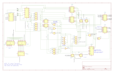
I rechecked my schematic, and RAS/CAS is not directly connected to a 244/373, and I found a discrepancy I forgot to add involving the Select + Strobe pins.

CAS/RAS 3 & 4 lead to a 157's outputs.

I thought that particular 157's Select pin (Pin 1) was not connected to anything, but doing some continuity, it's strangely connected through a 4.7kohm resistor directly to VCC! (To me, that doesn't make sense, unless it's supposed to be held high.) Also, there's a previously blank footprint for a resistor connected to the enable/strobe pin (pin 15), which I'm assuming is 4.7kohms as well, given that there are 3 resistors in the area (including one of those that is connected to the select pin).

I'm not sure if this means anything.

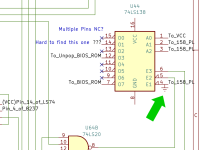
BTW, here's the area in-question on my schematic:

NtLaXEu.png
 
Last edited:
Would a logic schematic of everything up to the 138s help? (Unfortunately, the logic involved is information overload for me, so I wouldn't know where to start.)

I'm working on one right now.
 
While looking at my schematic, I found something odd.

One of the input lines on a 138 (U44), from a 158, is tied to ground. Assuming that this is not a mistake by me, is that the problem that I've been chasing all this time?
(I'll have to check with a multimeter later today. I know what happens when something is tied to ground. Some of the jumpers on this motherboard do that, disabling a chip's function.)

EDIT: IT IS TIED TO GROUND! I need someone to clarify if this would solve it!
 

Attachments

  • Sanyo Mem Schematic.png
    Sanyo Mem Schematic.png
    1.1 MB · Views: 6
  • Sanyo Mem Schematic closeup.png
    Sanyo Mem Schematic closeup.png
    192.4 KB · Views: 5
Last edited:
Okay, looking again, the 158 is supposed to be grounded. However, I don't know why that 138 is grounded too. According to two schematics I've seen (The 5160 and a Turbo XT Clone), pin 4 on that one 138 on my schematic isn't supposed to be tied to ground.
 
According to two schematics I've seen (The 5160 and a Turbo XT Clone), pin 4 on that one 138 on my schematic isn't supposed to be tied to ground.

Honestly, I think you're just making your life harder by cross-comparing the schematics of a computer that could be completely different from this one to the partial fragmentary bits you know about this one. If you really want to solve this you need to get a complete and accurate schematic of what the select circuitry of *this computer* is so you can understand what needs to change.

Here's about all I can manage here to try to help:

Comment the First:

Read the datasheet for the 74138 and try to wrap your head around what it does, I think it'll help you a lot. The '138 is a "3-8 decoder/demultiplexer"; what that means in TTL-speak is it's a thing that takes a three bit binary number on its inputs (pins 1-3, A0-2 on your kicad symbol), and if it's selected(* see below) sets the "O0-O7" pins so all but the one corresponding to that number are high. (Most TTL logic is "active low", and that includes the ouputs of this decoder.) That's all it does. If you slap one on a breadboard and wire 8 LEDs to the outputs and three switches to the inputs you can walk the switches through all eight possible positions and an LED corresponding to that binary number will light up; you will never have two LEDs lit up at the same time. If the chip is unselected all will be off.

(* assuming here you wired the LEDs with the cathode towards the decoder)

... So what do the those E1-3 lines do? They're the select lines. Look at the kicad symbol: two of them have that little triangle on the pin, the other doesn't. The triangle indicates "active low". So in other words, to "select" this chip you have to have two of these lines pulled down to TTL low (or ground) and one pulled up to TTL high (towards VCC). Why the world does this chip have three select lines instead of just one? Because this was a trick a lot of chips did so you could cut down on the total number of decoders. For instance, let's say you want to decode 16 lines, not just 8. (IE, instead of getting 8 unique states out of 3 input/address lines you want 16 out of four.) If these chips just had one enable line you'd need a separate 2:1 decoder upstream from them to switch which chip was active based on that fourth input line. But because of these select options you don't need that; instead you can connect the fourth input to the "high" enable line on one of the chips and one of the "low" enable lines on the other (while tying the remainder to ground or VCC as needed), and which chip is active will flip back and forth based on the status of that pin. Again, this is a trick common among decoders and small memory chips/ROMs in particular, things that you might want more than one of without having to stack multiple layers of decode.

... Anyway, long and short of it, when you see a '138 with one of the select lines tied to ground or pulled up to VCC then all that is telling you is that line wasn't needed to decide whether or not to enable this decoder. It is extremely reasonable and common to see '138s wired like this.

Comment the Second:

If you're right about ROM select lines being what comes out of this chip then I highly doubt it has anything to do with the RAM circuitry. At all.

Comment the Third:

Again, let's talk about the goal of reverse engineering the schematics, and for that I'm going to focus on the labels you put on U42. You labeled all three A0-A2 inputs and half the E-lines as coming from "To_BIOS_ROM". Knowing now that those are all *inputs* then, well, what exactly are those lines likely to be connected to on that BIOS ROM? Especially considering that the outputs of that '138 are largely connected to I/O chips? Maybe I should leave this one hanging, because finding the answer will arm you as to what you actually need to know to understand what you're looking at.

(Hint: This is going to be related to the answer for what signals run between U23 and U64B, which then contribute to the decision about whether or not those ROM sockets get turned on by U44...)
 
Okay, I traced those final points. Yes, U42 and U44 seem to not be related to the RAM.

The missing outputs for U44 I cannot find at the moment, if they are connected.

I know the pinout is not going to be the same from clone to clone, but I'm trying to find analogous structures on the board, without having to reinvent the wheel.
 

Attachments

  • Sanyo Mem Schematic 2.png
    Sanyo Mem Schematic 2.png
    1.2 MB · Views: 3
I'm getting close to figuring out what replaces the 24S10 in this system. I've already traced out the glue logic from the CPU.
 
Okay, I've narrowed it down to the 139 and 157. I included some extra circuitry, but highlighted the area of interest. I've also labeled where each already-known pin goes.
I am making an assumption that this layout, while different in pin input and output, is the same basic TTL structure as a 5160.

I've attached it as a PDF just to make sure that you can zoom into it.
 

Attachments

  • MEM SCHEMATIC1.pdf
    261 KB · Views: 2
There were some missing connections on the previous schematic, but I got them. I'm having another person on the Tech Tangents Discord take a look as well.
 

Attachments

  • Re-done Schematic.pdf
    397.5 KB · Views: 2
All right, after some time, I have had some help from an individual from the Tech Tangents Discord.

It seems that everything HAS been, for all intents and purposes, wired up already! There WAS logic for both 256k and 640k from the very beginning! All you need is an extra 158, an LS139, and, if you want, a few extra sockets for parity RAM and an S280 parity generator.

The central part of the logic, to switch between the 256k and 640k setup, was an LS157, and a jumper (J6/JP6) that grounds the 157's select pin. (Seen on the left side of the "Area of Interest" in the schematic)

View attachment Sanyo Mem Schematic RAS & CAS Fixed.png

Furthermore, I've been able to identify the RAM banks as well as their orientation! (This is just an example. My motherboard is fitted with sockets in all RAM footprints.)

sanyo memory locations.png


However, I am still running into problems, as both Supersoft and Ruud's diagnostic ROMS show consistent bit errors, even when swapping chips between bit positions in banks. This doesn't make sense to me, and suggests something else is wrong.
 
All right, to make sure that I was working with the least amount of memory as possible, I took out the memory, leaving bank 0 populated, and and set the only active bank to the same on the DIP switches. Doing some checking with the Supersoft Diagnostics, the memory starts having errors at address 05042 with an error on bit 7. I'm not sure how to interpret that, but after, it has errors at divisible addresses: 14001, 1C001, 24001, 2C001, etc. What would that mean? Is there something wrong with the addressing logic itself?

EDIT: Okay, I'm starting to think that it's the logic that's not working. The memory may be fine. Taking out the chips that previously weren't populated (139 and 158, to check with a chip tester) yielded something odd. The diagnostics still gave similar errors even with those logic chips unpopulated. I would expect the memory to not be able to be read ANY addresses/bits. Either that, or the Supersoft diags are limited.
 
Last edited:
Doing some checking with the Supersoft Diagnostics, the memory starts having errors at address 05042 with an error on bit 7. I'm not sure how to interpret that, ...
A displayed error address of 05040 is a known bug in the Supersoft Diagnostics ROM. You wrote "05042", not 05040. If that wasn't a typo, then like 05040, disregard 05042.

Note too that the Supersoft Diagnostics ROM does not know how much RAM you have fitted. It pays no attention to the settings of the memory related switches on the motherboard. On an XT-class computer, it often assumes that 640 KB is fitted. You can tell by the fact that "SYSTEM MEMORY TO A0000" is displayed (A0000h = 640K). Therefore, with less than 640 KB fitted, errors will be displayed when the diagnostic tests non-existent RAM.

Also, if there are multiple RAM errors, you will see a confusing display.

The better tool in your situation is Ruud's diagnostic ROM. Like the Supersoft Diagnostics ROM, it does not trust what is reads on the motherboard switches, however, Ruud's diagnostic ROM will do a decent job of determining (sizing) the amount of fitted RAM. When testing RAM, Ruud's diagnostic ROM will stop testing at the first RAM error. The concept is that you fix the displayed RAM problem, then re-run Ruud's diagnostic ROM to see if there is another RAM problem, and so on. More information at [here].
 
No, it wasn't a typo. It showed up as 05042. (It also showed 05040 without the logic chips installed)

Even so, with Ruud's Diags, I'm still getting consistent bit pattern errors (positions 1,3 and 5) even when the memory is swapped around, suggesting something's wrong with the logic.
 
Oh, and I forgot to mention, I'm getting false bit positives, even with the extra addressing ICs not installed, or completely without memory. (I would expect all bits to fail).
 
Oh, and I forgot to mention, I'm getting false bit positives, even with the extra addressing ICs not installed, or completely without memory. (I would expect all bits to fail).
My various IBM 5150/5160 motherboards behave differently to one another. For example, one consistently returns FC hex when I read a RAM address where there is no RAM. Imagine RAM test code that:
- Uses the test bytes of FF, 00, 55, and AA, in that order; and
- Aborts with an error at the first write/read failure.
On that motherboard, when FF gets written to the first no-RAM-exists address, FC is read back, and consequently, the test code reports bits 0 and 1 as faulty.

One expects that programmers allow for that kind of thing.
 
Last edited:
I'm still thinking it's a logic problem, because in the table below, these are the "bad" addresses that I got from the Supersoft Diag, and they increment every 8000h or 32768 decimal. (Correct me if I'm wrong, but that tells me that it's every 4 kilobytes.) Ruud's doesn't tell me anything further because it stops with an error at the first 2 kilobytes. (which is consistent with the 16K[ilobit] Critical Region popping up with an error with the Supersoft Diags. I know how the numbering systems work, it's just that neither diag specifies which is which, so I may be wrong on what kind of order-of-magnitude I'm talking about.)

HEXDEC
1400081920
1C000114688
24000147456
2C000180224
 
Last edited:
... these are the "bad" addresses that I got from the Supersoft Diag, and they increment every 8000h or 32768 decimal. (Correct me if I'm wrong, but that tells me that it's every 4 kilobytes.)
4 KB ?

You are dealing with addresses only. The data bit count per address doesn't come into play.
32768 dec ÷ 1024 dec = 32
 
The central part of the logic, to switch between the 256k and 640k setup, was an LS157, and a jumper (J6/JP6) that grounds the 157's select pin. (Seen on the left side of the "Area of Interest" in the schematic)
640K motherboard type: Two banks of 256 Kbit RAM chips, and two banks of 64 Kbit RAM chips. Have the required chip type in the corresponding banks ? An old friend of mine once accidentally got it wrong.

Does a 'bank 0 only' configuration work if you revert to a 256K motherboard type ?
 
One method of investigation:

Resources:
- Circuit diagram (and knowing how to interpret it).
- Parallel/LPT port diagnostic card.
- Logic probe.
- Logic analyser.
- Remove all RAM chips except those in bank 0, and set the motherboard switches to enable bank 0 only. (Looks like you have already done that.)

Create a custom BIOS ROM. In a loop, it would write and then read back the test values of 00 and FF (possibly 55 and AA as well) to address 0 (i.e. first address in bank 0), sending success/failure results to the parallel/LPT port diagnostic card.

If that test successful, I would successively adjust the test address until I saw a failure. (Which to software, will be somewhere in the first 2 KB according to Ruud's diagnostic.)
With the test code writing and reading the failure address, dive in with the logic probe and analyser, using the circuit diagram as my reference.
The first thing to look at would be the signals in and out of the RAM chips.
 
Does a 'bank 0 only' configuration work if you revert to a 256K motherboard type ?

Yes. In fact, the computer works just fine and reads "all" memory (that it can) if it is set as 256k. It only has problems if the jumper is closed. To me, that tells me that everything involving the 256k logic is fine. I'm still a bit iffy about the 640k logic, because I had some problems with a system timer when I first started messing with the memory in the first place. Mysteriously, it went away. I'm not sure if that means that something burned out, or it just fixed itself.

With the test code writing and reading the failure address, dive in with the logic probe and analyser, using the circuit diagram as my reference.

I'm planning on getting a DIP test clip, and a cable setup to adapt to my XGecu Pro IC Programmer. (Remember? It has logic IC testing.)

The first thing to look at would be the signals in and out of the RAM chips.
I was thinking about that myself. I want to test the logic first.
 
Back
Top