• Please review our updated Terms and Rules here

Plugging in power to other side..

Happy to post a teach-in...

Dave
Please do if you have the time! I think it would be hugely beneficial and I would be most appreciative. I think it would make a handy reference for novices and help all of us keep our vintage gear running. Part of my hesitancy in using this thing is just how overwhelming all the settings and options feel to someone who isn't an EE.
 
Reviving this thread as I now more or less understand how to operate my scope. Interestingly, on power up today this machine was showing signs of trying to operate.. lights were changing, etc.

I've wondered if the clock might be a problem. I can't remember exactly what oscillator they had installed before when I got it.. think it was 18mhz or something. I reverted to 6mhz which I understood from the article was correct.

With the scope now producing useful info, I probed the XTAL pins on the 8224. The frequency is coming back as 7.3mhz rather than 6.75mh. Also 7.3mhz at pin 12 (OSC). I don't know of that in and of itself is an issue, but I see the CPU is getting 830mhz to its phase 1 and 2 clocks.

The TTL pin on the 8224 is also showing around 830mhz rather than the anticipated 750mhz. I don't know if this causes a problem as I understand the 8080 was deliberately underclocked due to the slow 1702As.

Another note: the 8224 and 8080 get really warm.

I did a brief look at the data lines at the CPU, they definitely show signs of activity. Same with SYNC.

Also, when I inadvertently tapped the 8224
.. the indicator lights changed. They do not change when entering data though.

Anyway.. its late. Stopping for the night.
 
Last edited:
Being able to use an oscilloscope is one thing. However, the decimal point in numbers is very important, as is understanding the data sheets associated with the devices you are probing (in this case, the 8224).

The crystal is supposed to be 6.75 MHz. If the circuit is oscillating faster than that this may indicate that the crystal or 8224 has aged.

Beware of measuring the crystal itself with the oscilloscope though. The probe will load the signal up. If you have to do this, make sure you select the X10 mode on the probe. This will have the side effect of reducing the voltage that the oscilloscope sees by a factor of 10.

The CLK output is the place to measure, as this is buffered from the crystal circuit.

The phi1 and phi2 signals (feeding the CPU) are derived from the crystal frequency divided by 9. So (for a 6.75 MHz crystal) these should be 6.75 MHz / 9 = 0.75 MHz (or 750 kHz).

I suspect this is where you either have your units wrong (kHz instead of MHz) or are missing a decimal point!

The 8224 also generates the READY signal and a RESET signal.

Whilst probing the 8224, you should be checking out ALL of the functionality in one go...

Read the datasheet for the 8224...

Dave
 
Lol.. this is why I shouldn't be doing this stuff late at night. My wife being at home stops this from happening.

Yes, the signal I recorded was 830khz, not 830mhz.
I'll probe the whole chip, along with the CPU pins you mentioned previously, and see what I come up with when not rather tired.
 
OK, I made a video of what I was doing with the 8224 first.

One thing that jumped out at me was the OSC pin.. the soldercon socket that pin 12 of the 8224 plugged into apparently isn't making contact.. there is a signal on the IC pin but not the socket. These soldercon sockets are really easy to break or bend apart.

I think there are issues on other pins. As I was probing indicator lights would sometimes change. Soldercon should be straightforward to fix, albeit at the risk of damaging pads/traces. I don't know if I wouldn't be better to carefully solder the chip to the soldercon sockets.
 
You understood that pin 1 was RESET. If you look at the 8224 datasheet you will see that pin 2 is identified as /RESIN. The datasheet tells you this is Reset Input. The 'bar' indicates it is active LOW. So normally HIGH would be expected. If you observed a RESET output on pin 1 that is probably good enough to tell me that there is an input. Measure pin 2 again and press the RESET button - and compare the action with pin 1.

When probing, you require the schematic for the machine and the data sheet available.

If you look at the schematic for the machine, you should see that pins 2 and 3 of the 8224 are pulled up to +5V via a resistor. So, under normal circumstances, you should only observe a logic 'HIGH' on these pins.

The data sheet for the 8224 shows that READY IN (pin 3) - pulled up to 5V - becomes READY OUT on pin 4 to the CPU. If you are not getting a permanent HIGH on CPU pin 23 (READY) you have some bad connections somewhere.

I can't get excited at all about the OSC pin on pin 12 of the 8224 - as it is not physically connected to anything on the machine. So worrying about it accomplishes nothing...

You need good signals on the OUTPUT pins of the 8224 - but measure them both at the source (on the 8224) and the destination (e.g. the CPU)...

The other thing is that don't assume because you don't see any signal on the oscilloscope screen that there is nothing there... Rookie mistake! I see you adjusted the timebase knob and something did appear! Well done for that.

The data sheet also includes things such as the expected voltage outputs. Notice that the 8224 lists phi 1 and phi 2 (the clocks to the 8080) as 9.4 Volts (minimum) when HIGH. These are NOT TTL signals - and was indicated as so on your oscilloscope by the higher-than 5V observed signal. I think you missed that fact in your video. Again, it pays to check the data sheet. On another data sheet I found, it listed these two pins as MOS outputs as opposed to TTL outputs (as per pin 6 of the 8224).

By the way, generally (on schematics) inputs are drawn on the left and outputs are drawn on the right of a schematic. So, if you turn the machine schematic the correct way around, you can (generally) easily see what is an input and what is an output to a device.

Dave
 
Last edited:
Thanks Dave.

It's kind of like playing flight simulator a few times, and then someone dumps you in a real cockpit, and you have to remember all the procedures and where everything is.. hehe You forget basics like, hey, maybe having the schematic handy would help. I really should fire up my Designjet and print a huge copy of the schematic I can hang in front of me to observe easily.

Over time I've come to understand a bit more about how things are connected in a schematic and what to look for (ie. RESET, etc). But I still struggle with the why. Why this 6.8uf cap in the Bally power circuit doesn't matter, etc. There are some fundamentals I'm missing that would inform my schematic reading better - this is what I'm working on as I binge electronics basics videos. I have a tendency to dive in, because in most situations I learn better by doing. And sometimes that has worked out with my vintage gear, although I realize now a lot of that was just dumb luck.

I did take a quick look at the CPU before switching to other work - i do see both phase 1 and 2 clocks at 820kHz on the 8080, same as on the outputs of the 8224. I can also see activity on the data pins as well as address pins, although occasionally the latter drop to nothing, I assume as the CPU gives up trying to execute code. READY is permanently high.

I'm curious about how slow the 1702As are and how fast the CPU can go before they can't be read properly - ie if we need to bring the speed back down to 750kHz for the 8080 clocks, as the article indicates, or if there is some leeway.
 
There would have been some leeway - but the leeway may have already been eaten up by their age! Things (like EPROMS and humans) get slower with age. So if you now have a slightly faster clock signal - then that is a double-whammy.

Of course, you could always look up the data sheet for the 1702As and see what the data sheet says about the access time :)... Everything is written down somewhere...

Dave
 
Of course, you could always look up the data sheet for the 1702As and see what the data sheet says about the access time :)... Everything is written down somewhere...

Dave
Actually you'll be somewhat proud of me - looking at the datasheet was the first thing I did when I encountered this question. Unfortunately I am getting lost when it comes to understanding the relationship between access times (which is all the datasheet talks about) vs system clock speed. I'll have to do a bit more research to understand the relationship there.
 
The data sheet for the 8080 will have timing diagrams indicating a memory read transaction. The timing for the CPU is taken from there.

Dave
 
I did some reading and concluded it was prudent to at least try getting the clock to the 750kHz expected in the original article, just to eliminate that as a problem. I had another, newer 6750kHz crystal so that was easy to do. After verifying the signal was correct with the scope, I then took some time to read the theory of operation and consult schematics.

I decided to have a look at the memory select logic and device decoding. First I started with device decoding and consulted the explanation of how it works and the logic or truth table provided. I sort of grasp how this works and wanted to see what it was doing relative to the explanations. I don't know if it's possible to see exactly what it's doing with the scope, but I wanted to see if it appeared to be gating anything at all with the LEDs and keypad. So I took a look at the 74ls05 (IC17) and it seemed to be active on the pins indicated in the schematic.

Then I went to the memory select logic, and zeroed in on the 74LS155 (IC13). I wanted to see if there was any evidence it was trying to select PROM 0. And that's where I caught a problem.. the +5V pin was coming in around +4.2v. Looking closely I could see traces of green copper corrosion around on the +5V trace around the base of the soldercon pin, but continuity testing showed it was good. Nevertheless, despite being right next to a 74LS05 that had +4.95V, it still only had 4.2V. I then checked the ground pin and that turned out to be the problem.. a dry solderjoint had developed. The ground pin doesn't connect to anything on the underside of the board and the PCB isn't thru-plate, so the solder attaching the base of the soldercon pin was crucial. But it was broken off. Ended up replacing the pin although frustratingly the copper pad lifted from the PCB just as easily as others I'd tangled with had. Anyway I fixed it, and now IC13 has +4.95V. I rechecked voltages on all the other ICs.

Sadly this did not resolve the problem, although when you hit reset now the lights change. Something is still freezing up the machine, and I'm pretty sure there's more soldercon socket problems. But that's all I could do tonight.. I spent most of my available time just reading and poring over the schematic as well as some datasheets. It's a lot for a non-EE/electronics wiz to absorb. But I'm hopeful I'll get there - I think this is a good machine to learn with as it was specifically designed for learning. The explanations in the magazine are very well written. I'll do some more digging in between setting up the KIM to do its last test.
 
Last edited:
Well done!

This is the 'problem' for people who have learnt that just swapping chips fixes a machine. It can do in quite a number of machines. But, when there is more than one fault present, or the fault is more convoluted, swapping chips does not work. After that, people are stuck...

For cards at work, I have put together a repair kit. I ask people to measure the power rails and the clock signals on a faulty board first (by following a procedure I have written) and then, if those are OK, to swap all the socketed chips for the specially labelled parts in the repair kit. If the card now works, they can follow my documented procedure to find (and replace) the faulty chip(s) to get the card working again. If the card doesn't work, they send it back to the manufacturer who will use their ATE (Automatic Test Equipment) to pinpoint the faulty component(s) and effect a repair.

People 'think' that reading and learning is a waste of time, but (as you are seeing) it provides a wealth of knowledge that is invaluable to aid fixing the more obscure faults and will assist further learning in the future. Learn the basics and then build on the basics. You cannot become an expert overnight, you have to work at it...

That is the good thing about a construction magazine, they provide a good description of how something works.

Stick with it, and keep asking questions. You will get there!

Dave
 
Last edited:
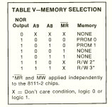
Thanks Dave! My one question right now is.. should I be able to see, for example, on IC13 per this table, the PROM etc actually being selected? Can a scope see that? Or is it just going to show me that *something* is happening on the relevant pins?
 

Attachments

  • Screenshot_20240106_074712_Adobe Acrobat.jpg
    Screenshot_20240106_074712_Adobe Acrobat.jpg
    178.7 KB · Views: 0
Of course it can!

That is the whole purpose of an oscilloscope!

If you have a digital oscilloscope, you should be able to set it up as a single shot trigger.

Let us say that the EPROM has an active LOW chip select line. You setup the trigger for the high to low transition. The oscilloscope should then trigger once to capture one chip select activity for detailed examination.

You can then set the trigger to normal, and you should observe a trail of signals - each as the EPROM is selected.

This is half the battle with an oscilloscope. You can aimlessly probe around (!) or you know what should be there, and configure the oscilloscope to capture what you know should be there.

Dave
 
In fact, there is no signal on that machine (or any of your machines come to think of it) that you shouldn't be able to measure.

The only exception will be high voltages, and you can if you buy a high voltage probe.

The trick is working out a trigger...

Sometimes I have to resort to a bit of external TTL logic to devise a trigger signal. But these conditions are very rare.

Dave
 
To be fair, the proper tool for investigating the presence/absence of signals here may be a logic analyzer, although the difference between a modern multi-channel DSO and an LA may not be significant for tasks such as this.
 
With all of these poor connections I disagree. You need something in the analogue domain to start with. A LA will just mask rubbish signals in the first instance.

Dave
 
Back
Top