• Please review our updated Terms and Rules here

Starting my first Pet, a 4032 in desperate need of some love

Yes, looks like $C ROM is bad, do you have any 2532 EPROMs ?

Did you let the memory test run and was it testing board memory or ROMULATOR memory ?
 
I did not let it run since i know i have a bad ram chip. I replaced 8 bad ones but the 9th is waiting for more to come.

I also need to replace the edit rom. I only have 2764 and 27256 eproms. I also have not burned an eprom in decades and I only have 2 untested burners, 1 on an untested 286 and one for a c64. I'll get started testing and looking into options this week...
 
If you adjust your monitor, PETTESTER will probably state that it has detected 16K of RAM - if your faulty chip is in the upper 16K bank of RAM.

In this case, the memory test will only test the lower 16K of RAM and that will be a valid test.

Dave
 
I'll give it a try in the morning. The bad ram actually makes it through the retro chip testers first 4 tests before failing so I'd guess that it will think i have a full 32k. If i remember correctly it fails on a March-c test.
I was playing with it this morning and was able to see the screen better. A couple keyboard outputs are changing even with the keyboard unplugged. I'm suspecting some of the glue logic but we'll test and see.
Also the c rom value changes each cycle so it may be the stick in the spokes and will be removed next. The other rom crcs seem to be stable and correct.

Mike
 
If the C ROM is changing then that has to be replaced before we can get BASIG running.

If the KBD line on the PETTESTER is changing, then that could indicate a faulty keyboard PIA, but let's leave that problem to later shall we...

We can tell (from the MARCH-C address) which bank and bit is failing, so it will give us some useful data nonetheless.

Dave
I know exactly which ram is bad. I pulled them all and tested each in the tester. I had 8 spares so it had to have 9 bad ones of course. I put the bad one in the first upper Bank socket so it can be replaced once more come in (UA4?). The lower bank is now all nos ics that test good.
 
The best IC's are the TMS2532JL (not the 2532A). Like these for example and a great price for only $5 each:


I would suggest getting some of these and some vintage 2716's and making yourself a set of known good ROM's. They come in very handy for service work.

Try to find vintage 2716's with the large sized die in them and early date codes, like this for example, and you will have no troubles:

 
A word of caution, these '25' type EPROMs with the different pinout from the ubiquitous '27' series EPROMs only had a relatively short production life, they were, if you like, the Betamaxes of the EPROM world and were quickly sidelined by the 27xx series. Because of this, only the oldest low end or 'regular' EPROM programmers or, in modern programmers, the higher end ones, actually support the 25xx series properly so check that your device programmers actually can 'do' them. If not, you might be better off using 2716s and 2732s with pinout adaptors.

If you can't program 25xx EPROMs with your own programmer but would prefer to use them anyway to avoid having to use adaptors, I'm sure you can find a friendly 'local' here on the forum who has a capable programmer.
The common garden GQ-4x programmer can do both the 2716 and the 2532JL. I think the pin adapters are a nuisance and they have to be ones that don't damage the sockets. A while back I built something with a 2732 that was originally designed for 2532 style pinning, so I altered the pcb with solder bridges to make switches to allow for both types, but I wished in the end I had just used the 2532. There still seems to be plenty of good vintage 2532JL's about, the thing is to avoid the 2532A these are a PITA to program and many people have had a lot of trouble with them, especially in the video arcade game industry. You can get the GQ-4x to do it by selecting a 2732A and making a pin adapter, but it is very messy compared to using a 2532JL.
 
The common garden GQ-4x programmer can do both the 2716 and the 2532JL. I think the pin adapters are a nuisance and they have to be ones that don't damage the sockets. A while back I built something with a 2732 that was originally designed for 2532 style pinning, so I altered the pcb with solder bridges to make switches to allow for both types, but I wished in the end I had just used the 2532. There still seems to be plenty of good vintage 2532JL's about, the thing is to avoid the 2532A these are a PITA to program and many people have had a lot of trouble with them, especially in the video arcade game industry. You can get the GQ-4x to do it by selecting a 2732A and making a pin adapter, but it is very messy compared to using a 2532JL.
Don't laugh but my plan is to use a Promanade C1 on my commodore 128. It's close to what i used back in the day and i think i have everything i need. Ihave verified in the manual that it supports 25xx eproms. I'll download the .bin and save on the SD2IEC then I'll edit in the load address bytes with Hesmon. I think this should work while making do with what i have and enjoying a nice retro experience.

My backup plan is that I'm going to the PDX Commodore users group meeting on May 5th and can burn them there if i have not succeeded. I'm hoping to take the pet to the meeting since I'm getting the reproduction label there and they are who originally gave me the pet (Sean / Geek with Social Skills is the president). They also have a 1987 newsletter from the middle school this pet was used in that was in another of the 4 they recieved. One member said they thought they were beyond reasonable repair but after my video are getting right to work on another one...

I have to say I'm really loving the Pet. It really fits into my level of skill on the digital side. At least where my skill was back in the day.

I also really appreciate all your support (everyone here). This project has really started to bring me closer to where i was back then.

Mike
 
>>> I also really appreciate all your support (everyone here). This project has really started to bring me closer to where i was back then.

You're welcome!

Dave
 
I adjusted the monitor and it was only detecting 16k of RAM. I got in my replacements today and swapped out the bad IC but it is still only showing 16k. I inadvertantly did a 36 hour test on the machine where it was running on my bench doing the PETTESTER RAM test the entire time so perhaps another upper bank chip has failed. I will check the chips then start checking the associated ICs if that doesn't fix it.

Mike
 
My PETTESTER does a very quick look at memory. If it doesn't find a valid data byte it can write to and correctly read from at address $4000 (the first byte of the second 16K bank) it assumes the upper 16K bank is not there and refuses to test it.

Dave
 
One thing about the PET dynamic RAM memory control system & refresh , it is constantly active with the computer doing nothing. So you can easily scope the control signals and make sure they are working.

It is possible the upper bank is not being activated by a problem in the select jumpers/ switches if there has been some corrosion. Or a problem in the select logic. At least none of the IC's in the upper bank have a stuck high or low output bit, if they do it corrupts the lower bank and it wouldn't boot.

If it is of any use, I scope recorded most of the dynamic RAM control signals for the 4116's in my PET, over 20 scope photos which show what the signals should look like in a 32k PET, they are in this article pages 6 & 7:

www.worldphaco.com/uploads/DRAM%20MEMORY%20TEST%20SYSTEM%20FOR%20THE%20DYNAMIC%20PET%20COMPUTER.pdf
 
The EPROMS came in, I accidentally ordered 2716s so they had to be reordered. The NoS 2532s are not erased and i just discovered that the old EPROM eraser I was given recently had the leakiest batteries I have ever seen in it. The Circuit board and tube were absolutely destroyed. Now I am trying a hail-mary. EPROMS prefer a wavelength of 253.7nm but on one old datasheet it said that up to 400nm will erase them so I am trying a black light I have on hand that is 395-405nm.

I do have the Promenade C1 working on the C64 now too. I think I have the 2 byte issue worked out too by checking the first 2 bytes of the .bin file with the visual studio code hex editor. I can then load the file into RAM on the C64 starting at the address I want to use +2 then poke the missing 2 values in. I am considering making a simple tool on the C64 in assembly for loading them into memory.

I am glad now that I went this route instead of buying a new burner that I cannot afford at the moment!

Mike
 
OOPS, I forgot that the Promenade C1 Requires that 24 pin chips go in to the right side of the socket even though the Pin one side goes to the left. These ICs are all erased and appear fine.

Mike
 
One thing about the PET dynamic RAM memory control system & refresh , it is constantly active with the computer doing nothing. So you can easily scope the control signals and make sure they are working.

The other thing about the pet DRAM refresh, PETTEST is fast enough (until V5 :) ) to refresh it so that it doesn't throw up errors and the machine will successfully start up then start showing some really odd errors as you try to use it.
 
The other thing about the pet DRAM refresh, PETTEST is fast enough (until V5 :) ) to refresh it so that it doesn't throw up errors and the machine will successfully start up then start showing some really odd errors as you try to use it.
Possibly, if the machine is throwing up odd errors when you go to use it, there could be something wrong with the lower bank, which has to be perfect to properly support BASIC, which relies on the lower 1k being perfect and preferably the lower 2k too for small programs. The lower memory might be ok initially and allow the boot, but could play up later with refresh issues.

That is why in the diagnostic system I cooked up, the DRAM is disabled under 1k or 2k, and replaced with stand in known good SRAM, so BASIC will definitely be supported and run without errors. And then the DRAM memory above that can be examined for defects. And if the replacement of DRAM with SRAM cures any issues, there must be a defect in the lower DRAM memory locations.
 
In my SK, the whole DRAM refresh counter failed. It would pass PETTEST with no errors and when switched on, would show the startup banner and a flashing cursor.

When you did anything in immediate mode, like PRINT A, it would work but as soon as you typed in a program things got really weird :) (like decimal point line numbers) and would usually crash.

Had me scratching my head for a while
 
OK all the ROMS are in and I finally have good checksums on everything.

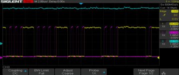
I am starting in on the RAM issue and so far have found that /CAS_1 is always high. Checking the 74LS00 at UD5 I found that the inputs to the NAND gate that puts out /CAS_1 are both active but are never both high at the same time so I will start tracing backwards from there. The signals also seem a bit weak at about 4v so something is probably pulling things down a bit too.

CAS_1_UD5_P11_12_13.jpg
Purple and Yellow are inputs (Pins 12 and 13 uf UD5), Blue is output (Pin 11). 1v per div but inputs are offset about -3v and output by -1.2v for ease of viewing. Timing is 2uS per div

edit: Out of curiosity I pulled off the pet tester to see where it was at with just a 6502 and it boots to a flashing cursor with 16K of RAM. The keyboard matrix has issues though with some keys providing the wrong result and others not working at all (Stems?). I will have to put it together so I can get good enough access to test all the keys and see what they do so I can decode the issues on the matrix.

Mike
 
Last edited:
Back
Top