• Please review our updated Terms and Rules here

Starting my first Pet, a 4032 in desperate need of some love

First thing is the output from the on-monitor-board voltage regulator (but that will probably be OK if the heater is lit).

Yes, the old fusible resistors would probably be your first point of call! These can be 'seen' - so no high voltages around to bite you!

Dave
 
They do indeed appear to be open, I will double check in a bit when I remove the VDU from the case. I don't have any low wattage 56 or 68 ohm resistors. I have some old 47 ohm ones that are either 1/4 or 1/8 watt but I am not sure if they are metal or carbon.

I expect that they should be OK for troubleshooting with correct ones put in once they come in.

Mike
 
One was open and the other was reading 400 ohms. I installed the 2 47 ohm resistors as a temporary fix but there was no change. Still no High Voltage. I will dig in tomorrow since i have commitments for the rest of the day

Mike
 
Mike, can you re-post a link to the schematic for your VDU.

I had a feeling on these ones that there were 3 fusible resistors, but I would have to check the schematic.
 
Mike, can you re-post a link to the schematic for your VDU.

I had a feeling on these ones that there were 3 fusible resistors, but I would have to check the schematic.
Doh I found it half buried in white goo holding a cap. R751 looks like 2.2 ohm on the schematic. I pulled the board and it checks out OK at 2.6 ohms

I am using the 321448 schematic in the 8032 manual. I am mainly using a hard copy 8032 original manual since it is easier to read then the scanned ones. When I need to go 4032 specific then I have a downloaded copy stored locally.

Mike
 
Take a recording of the collector voltage of the output transistor you replaced. It needs to be with a x10 probe which can handle around 400v. There should be a flyback voltage spike there. In a transistor 12" monochrome set this can be as high as a few hundred volts. In a color set it can be as high as 1kV and requires a x100 probe. If you look at the green trace on post #42 of this thread you can see a collector voltage recording , this one is about 150v:

 
Last edited:
It might have been a little bit premature to replace the original, albeit rusty transistor, metal cased transistors, even the common or garden 2N3055, are so widely faked these days that you can never be sure anything bought now is real. I don't know where you bought the replacement device from?

Do you have some means by which to check that the replacement transistor is good, a component tester / analyser perhaps? Can you also test the original device out of circuit to see if its 'signature' is similar to / identical to the replacement device? At the very least both devices should 'look' like a pair of diodes when tested from base to collector and from base to emitter with the 'diode test' feature on a DMM (that's with at least two out of three terminals disconnected from the surrounding circuit).
 
Last edited:
It might have been a little bit premature to replace the original, albeit rusty transistor, metal cased transistors, even the common or garden 2N3055, are so widely faked these days that you can never be sure anything bought now is real. I don't know where you bought the replacement device from?
I got a pair off ebay from this auction
https://www.ebay.com/itm/3011701758...DDv7yYT_2&var=&widget_ver=artemis&media=EMAIL

Do you have some means by which to check that the replacement transistor is good, a component tester / analyser perhaps? Can you also test the original device out of circuit to see if its 'signature' is similar to / identical to the replacement device? At the very least both devices should 'look' like a pair of diodes when tested from base to collector and from base to emitter with the 'diode test' feature on a DMM (that's with at least two out of three terminals disconnected from the surrounding circuit).
My only tester is an extremely cheap device but it may suffice. I bought 2 so i will test the other one to start with.

I'm dealing with offers on my dad's house tonight so i may not be able to get out to the shop until tomorrow. Once i do I'll test the transistors and, if it looks OK the signal.

I was just getting ready to test the doused diodes and transistors in circuit. If they don't look right i can usually tell from the schematic if it needs pulled and retested.... at least until it doesn't.

Mike
 
Those are genuine Hitachi parts and have no hallmarks of fakery. There should not be any problems with that, unless the base & emitter connections got accidentally swapped. You can check the schematic. Mostly they used a black or blue wire for the emitter connection, and a yellow for the base. If you could take a photo of the area, I can check that for you.
 
Those are genuine Hitachi parts and have no hallmarks of fakery. There should not be any problems with that, unless the base & emitter connections got accidentally swapped. You can check the schematic. Mostly they used a black or blue wire for the emitter connection, and a yellow for the base. If you could take a photo of the area, I can check that for you.
I will double check but I'm sure they are correct. The board is marked and i used the data sheet to verify. I was paranoid about getting something wrong on an analog board which is not my greatest strength

Mike
 
The usual thing where there is no activity and high voltage is to trace the H drive signal through with the scope to the base-emitter junction of this transistor and do a test on the collector waveform with the scope. And confirm that the power supply connection on the primary side of the horizontal output transformer is present. To cut to the chase the first thing is to measure the collector waveform with the x10 probe & scope and the result of that dictates what to do and where to check next.

PS: the scope with the x10 probe needs to be on DC coupling and set the no signal trace to about 1 division from the bottom of the screen.
 
Last edited:
OK I checked and there was nothing but a little noise on the collector. I then checked the HSYNC input on the VDU connector and nothing. Nothing on the VSYNC pin either.

I Disconnected the VDU from the main board and still nothing on J7. After some fiddling I decided to recreate the original conditions where I had a signal by disconnecting the only other thing that was not connected then, the keyboard.

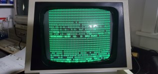
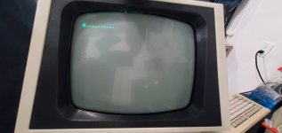
Then the signals returned and, with the VDU connected, I now have a screen full of beautiful, beautiful garbage!
20230406_143747.jpg
 
OK I checked and there was nothing but a little noise on the collector. I then checked the HSYNC input on the VDU connector and nothing. Nothing on the VSYNC pin either.

I Disconnected the VDU from the main board and still nothing on J7. After some fiddling I decided to recreate the original conditions where I had a signal by disconnecting the only other thing that was not connected then, the keyboard.

Then the signals returned and, with the VDU connected, I now have a screen full of beautiful, beautiful garbage!
View attachment 1255135

That is good, no VDU problem now the CRT looks goods, all you need to do is reduce the height a little.

Now the fun begins fault finding the main board !
 
Hmm, not sure why the keyboard should interact with the VDU like that. But I'll think on it...

I assume that is my PETTESTER running? If so, the low RAM bank looks shot (at a guess).

Dave
 
My gut reaction is to socket the RAM and ROMs since they are all extremely corroded.

Are there any tests I should look at first before potentially adding other issues by de-soldering the corroded chips? (Always a possibility when working on a board which is why I have waited). Once the machine is working properly it is my thought to socket/replace ICs with extreme rust. This board has been surprisingly pleasant to solder on so I am confident it can be done with little or no damage.

My only thought on the keyboard is that the left shift key is effectively being held since there is no spring or key present.

Mike

edit:I have enough RAM on hand to replace half the chips. I have no EPROM burner newer than 20 years old and I have never tried to use the ones I have (One is on a 80206 and another is for the C64). I also don't have any 2716s but I do have a TON of NoS 2764s

Also there are a few characters in the middle of the screen that are changing.
 
I pulled out the board and got everything ready to socket the RAMs in the morning. I did find that pin 2 (RDY) on the ROMulator socket had bent under but correcting that made no difference.

From what I can tell that pin is always held high on the pet so, since it was not connected, it would have been floating. It looks like RDY may not do anything until a negative going transition so that allowed the processor to run? Seems a bit odd to me but thats all I can find to explain why the processor was running (Unless its something specific to the PETTESTER?)

edit: I suppose it is also possible the bent under pin was still making contact in the socket.

Mike
 
With badly corroded IC pins and solder on the pcb heavily oxidized, it helps a lot to add a good amount of fresh solder to each pin and pcb pad area initially, before the de-soldering process. We are all enjoying watching your PET come back from the dead.
 
Finally got the last RAM chip out. According to the Retro Chip Tester Pro 8 of the 16 chips are bad. I have a ton to do this weekend so I doubt I can get the board top cleaned of its crusty bits and install sockets until Monday... Sigh, damn RL
 
I had 8 NoS 4116 RAMs on hand so, of course, there ended up being 9 bad ones. I put the new chips in the Odd (Lower) bank and ordered 16 more but they wont be here for about a week. I think I will try testing it with one that doesn't fail until the RND test in the high bank since it must not have contention issues if it passes the 1111, 0000, 1010, & 0101 tests.
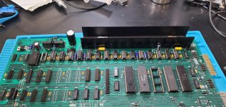
20230408_112358 - Copy.jpg
20230408_114144 - Copy.jpg
edit: It has a very similar screen but with a little more activity, especially at the bottom of the screen and many of the b characters from before are now g. This doesn;t really surprise me since the ROMs are bound to be causing bus issues given their current state. Next I'll get them off the machine so the ROMulator can do it's thing.
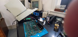
20230408_114131 - Copy.jpg
 
Last edited:
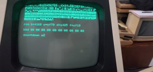
OK Progress. I pulled the video RAM since the Regular RAM had a failure rate >50% and a friend called suggesting it may be the issue but both were OK. Then I pulled UD6 off the board and now we have PETTESTER! UD6 tests bad with a different CRC every test.
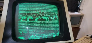
20230408_213630.jpg
Sorry for the potato picture, the Pet is open and facing the back of my bench so I was shooting blind

20230408_213806.jpg
After a while it went to this but comes back up after a restart. Edit: Lol - PETTESTER Memory test - I need to adjust the monitor

Mike

edit> with the romulator set to Basic 4, CRTC, 40C I get a boot screen with 31743 bytes... Of course thats in the ROMULATOR as I understand it.

Also if I am reading the PETTESTER Docs (that I Finally found) correctly then it looks Like the $C000- ROM at UD9 is also bad
 
Last edited:
Back
Top