UPdate
UPdate
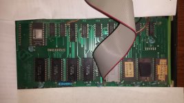
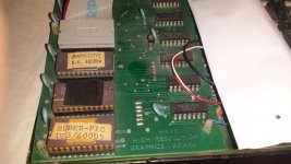
With the help from Steve Gray, Mike Naberezny & David Viner, this is what we did to get my Supersoft HR-40(B) High resolution Graphics board working (Caution:- I have no idea if there are differences between HR-40(b) boards or other variants so this applies to my setup only).
Installation for my board
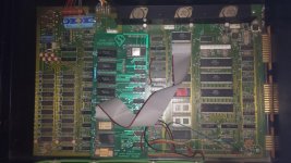
My board came already installed onto a non working 4032 Motherboard but I wasn't sure that some of the connections were correct. I found a post by Anti Florian on CBM-Hackers where possible connections were listed
http://www.softwolves.com/arkiv/cbm-hackers/13/13565.html
These were almost identical to mine, which gave me confidence they were right. Exceptions were, UB8 wasn't available on my board (80 column only) so I selected UB3 instead.
Also on my board I wasn't sure of the correct location for the blue DIP header (as mine appeared to be 1 pin down on the 6454 CRTC IC. ie pin 1 of the DIL aligned with pin 4 of the 6454 instead of pin 3 suggested in the post). I therefore tried those suggested in the post (as it made more sense). My connections are summarised below starting with a "standard" motherboard board configuration
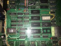
• Removed the edit and character ROMS from UA3 / UD7
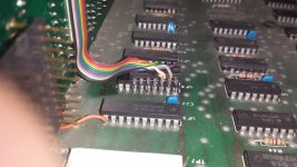
• Clipped Red wire to Pin 11 UB3
View attachment 38913
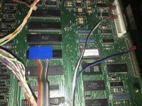
• Connected the board by pushing the 2 headers into the respective UA3/UD7 sockets
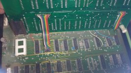
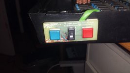
• Clipped the Yellow wire to Pin 11 of UE4
• Connected Blue/Purple wire into Pin 17/18 of J4. Purple to Pin 18
View attachment 38914
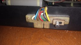
• Connected Grey wire to Pin 14 of J9
• Connected White and Black cable to Pin 21/22 of J9. Black to Pin 22
View attachment 38915
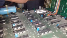
• Connected the Blue DIL adapter onto CRTC IC 6545
o Pin 1 of the DIL aligned with Pin 3 of the CRTC chip
o Pins 2 – 11 of the DIL then connected to TA0-TA9 (Pin 4 – 13 on CRTC)
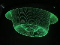
Steve disassembled the ROM and found $EFFF may be a write register. There was a review article from the ICPUG magazine which gave a basic description and detail about how the board worked and included an example draw command which I tried. Steve's disassembled code identified other potential draw commands though the syntax was not clear (more trial and error to follow entering commands to see what happened)
Display Modes
With help from Mike and Steve, we started to try out different settings through trial and error.....
The register appears to have 5 modes available. To set the register
POKE 61439, n where the integer number n =
Below is what I have found from trial and error ...
n=1: Use the On-board 8K RAM for own programmes – address $9000- $AFFF
n=2: Blank screen but can still draw and write text but nothing will be shown until you poke register
with 5 or 7
n=5: Basic Text and Graphics
n=7: Graphics NO text
n=8: Access On-board Option ROMs at $A000 and $9000 – no graphics. Graphics ram appears to be preserved so when select 5 or 7 it reappears.
We also confirmed by writing directly to the boards RAM that it was indeed working.
Draw Commands
HR = 59650.
View attachment 38916
Scan Courtesy of David Viner - this article is the best we have to date on the commands available.
Mike is starting a Web Page to document this further with additional information as there is far too much to cover in this post
http://mikenaberezny.com/hardware/pet-cbm/supersoft-graphics-board/
A very big thank you to Mike, Steve and David for helping me out here - great teamwork & support as it wasn't easy!

