• Please review our updated Terms and Rules here

Vectrex (newer version - no buzz) - Troubleshooting Sound but no Video

Hi

After 2 months being quiet here I want to give another update. You may wonder what happened to my poor Vectrex…

In fact I did not have much time for fixing that console as the spring arrived and I was busy with bigger constructions in my backyard. Still found a few minutes sometimes to follow up. I socketed all Chips in question on the digital board and was using the trial and fail method by changing Chips but without success.
Still no video and sound. As I already ordered all the electrolytic capacitors months ago I wondered why not replaced them now and take it from there?

The recap went fine without lifting a trace or damaging a soldering pad. However I found already missing pads on the analog board at C507 and C508. I soldered the new caps on the upper side on the board and checked continuity which was fine. Unfortunately I broke the LM7905CT voltage regulator while removing the big heat sink. But still got a 7905CP in my inventory and soldered that one in. Could not find the difference between CT and CP and hope that’s ok.

Today was the day when I carefully re- assembled the Vectrex and flipped the switch. First I tried without having the digital board connected. Wanted to measure the DC voltages first to see whether these are ok. But no sign of life. I could not measure AC power at the analog board nor at the switch. Found the main fuse blown.
I tried to find the reason on the analog board why the fuse was blown but all looked ok. All capacitors are orientated correct. Hmm. Unfortunately I did not found another 0,5 amp fuse but a 4 amp fuse. Tried to start the unit again. This time I measured around 5 VAC at the board. Much too low. Now the transformer is making noise. Getting louder. Not good. My Power Meter shows that the sick Vectrex pulls above 300 Watt. Too much. Now it’s also giving smoke signals like it’s passing away. I completely removed the power. All this happened in less than a minute. Quite an experience and never happened to me Yet. So, be warned - never use a too big fuse :confused:

After a break and cooling down myself I completely desoldered the transformer off the switch and tried to run the transformer alone. Same story. It’s pulling a lot of power and is getting just warm.

So, my bad luck with this Vectrex continues. Looks like the Transformer is dead. Can anyone suggest a replacement? I am now wondering whether the new caps or the 7905 replacement has caused the transformers dead?

I am now back in my garden. Seems to be a safer place, haha 😆

greetings from Germany
Denis
 
Hi,

I like to share an update on my Vectrex.

I received a new transformer from china (via ebay - 50W, Dual 9V outlet: https://www.ebay.de/itm/404290127716?var=674194324730) which looks suitable in size and given maximum current. And with a bit of modifying of the mounting holes it fits inside. After installation of the new transformer and a proper 0,5A fuse I only connected it to the switch but kept the wires to EP104, EP105 and EP106 of the power board still disconnected. After switching on I could measure ca. 11 VAC on both wires versus the neutral wire. Looks good. No fuse blown yet.

Next I soldered all 3 wires to EP104, EP105 and EP106 and kept the plug to J204 at the logic board disconnected. Switched the unit on - fuse blown!
Ok. Just connected the wires to EP104 and EP105 and switched on - fuse blown! Same story when connecting to EP105 and EP106 only - fuse blown!

Now I checked the rectifier diodes D101, D102, D103, D104 with my component tester while having the DC sider unsoldered following advise of Daver2 on the other blown issue thread here (https://forum.vcfed.org/index.php?threads/vectrex-blows-internal-fuse-after-time.1242902/)
All Diodes tested ok.

So I followed the path and checked my new installed big electrolytic capacitors C109, C119, C117, C118. I noticed a possible shortcut across C109 and C119 when measuring resistance. From my experience the ohm reading should increase over time indicating the capacitors are charging up. That behaviour I found when measuring across C117 and C118. But not at C109 and C119. Strange. I desoldered C109 and C119 and tested with my component tester. Both tested ok.

I measured again restistance between the pin holes of these capacitors before I soldering them back in. Found still a short! 0,001 Ohms. Not good. Following the path brought me to my 7905 which I installed recently (see post #41). Desoldered that thing. No short anymore. Switched on the vectrex with a new fuse. This time it did not blow!

So, obviously that 7905 replacement is faulty or the wrong type? I dont understand. I have checked the datasheets between the original LM7905CT vs. my replacement L7905CV. The pinout look the same on both. Maybe it is faulty although brand new? Maybe I have found the culprit for the blown fuse or something behind that regulator is pulling too much current?
 
Last edited:
The 7905 is installed the right way round isn't it?

Does this 7905 have a metal tab? If so, is that shorting to anything?

Dave
 
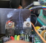
oh. good point. The metal tab actually hits the heat sink. its installed like the +5,0 VDC next to it. I installed the 7905 the same way as the other one before.

IMG_9098.jpg
 
Ah ha...

The metal tab of the LM340T is either "GND" or "VOUT".

The metal tab of the L7905CV is "VIN".

If you have them both on a metal heatsink, with no insulation, you have a short circuit.

The L7905CV (as you have bought) has the metal tab connected to VIN as I have stated. You can purchase a part that has an insulated metal tab.

You either (a) need to purchase a part with the metal tab insulated or (b) fit mica washers and insulated bushings to isolate the metal tab from the heatsink.

You can test which pin the metal tab is connected to with a multimeter...

I hate negative voltage regulators!

Dave
 
You are absolutely right. Thanks for pointing me in the right direction, Dave:)

indeed the input and the metal tab on that 7905 are joined together. I had no glue about this. I thought the metal tab is GND. Also overseen that in the data sheet. Now I know and also don’t like negative regulators anymore… they are so negative :mad: Haha 😆

The metal tab on the LM340T is connected to GND. No issue here.

However - this fuse problem is fixed after I insulated the 7905 and now I can start the unit and read all voltages again. Great 😊 But the Vectrex is still not functioning. But at least it is fully recapped and many chips are socketed now. Will start looking again with my scope and will let you know. Unfortunately I need to go on business travel again….
 
Last edited:
Oh well, hopefully the blown fuses are now a thing of the past!

I have just come back from a business trip... Enjoyable, but very tiring!

Reconvene upon your return.

Dave
 
Hi,

So, got some time this weekend to follow up.

Yesterday I took my god working Vectrex and used it for testing of all the socketed chips from the faulty unit - one by one. I was able to verify these chips working properly in my good unit: IC301, IC302, IC303, IC207 (6522) and IC208 (AY3-8912 soundchip). I got always MineStorm up and running with sound. So, we can actually rule these chips out being the root cause for the faulty Vectrex.

The current status is as mentioned before - no video and no game sound (just a quirky sound going up and down the frequencies). However I believe the computer/Minestorm is working in the background as I can see activities on the 3 sound channel outputs (Pin 1,4,5) on IC208. Which is a good start I guess :)

So, starting the troubleshooting all over again. Checked AC and DC Voltages at the power supply board. All good!
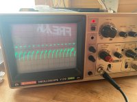
Used my test cart and scoped the X,Y and Z at J401 (logic board) and at the landing points at the power board. They look all good, same picture as in the troubleshooting manual.

Then I checked the supply voltages at the CRT PCB (EP501 - EP505). Found some obvious problems here:

A) I measured 53,7 VDC at EP505 (should be +40)
B) EP503 is oszillating around zero (mainly just below 0) and EP504 is at 0,0 VDC and the value is not changing at all on either of those when turning the brightness knob, according to the manual it should move between -29VDC up to +3VDC. Not sure which Pin is meant but it is one of these 2 - so this is definitly wrong behaviour
C) I measured 157,6 VDC at EP501 (should be +135)

Next I scoped EP505. The manual says I should see the Z-Axis waveform there. But I don´t. It is a flat line at above 50 VDC only. This is definitly not correct.

So my problem is obviously that I am missing the Z-Axis at the CRT and therefore there is no picture. The manual says there could be IC302 or IC303 faulty. These are ruled out already, And they say it could be Q503 or/and Q505 faulty. How can I trst them?

Why there is no sound is another mystery. When I received the unit I still got sound but I lost it after replacing the electrolytic capacitors on the logic board.

Do you have any suggestion how to move on from here?

thank you
best regards
Denis
 
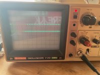
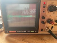
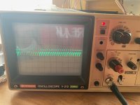
Looked around the transistors Q503, Q504 and Q505. I can clearly see the Z-Axis Signal going in (Q505-B) and coming out (Q505-E). Looks normal, right? I guess this transistor is ok. Not sure about the other ones. The waveform on Q505-C (shared connection with Q504-E and Q503-E) looks weird. Maybe I should replace Q503 and Q504 both?

Q505-B.jpeg

Q505-E.jpeg
Q505-C.jpeg
Q505-C Zoom.jpeg
 
Hi,

I have seen your posts, but am somewhat busy today with other things.

If my understanding of your oscilloscope traces are correct, you are getting less out of a transistor than you are putting in. Is that correct?

Just because a waveform looks weird doesn't mean it is wrong - especially if there are capacitors and/or inductors involved (i.e. a CRT circuit).

Dave
 
For the sound I would suggest looking at these points:

+9V DC on IC103 pin 6.

An input signal on IC103 pin 3.

An output signal on IC103 pin 5.

After that I would check C114 and then the speaker itself. Disconnect the speaker and check the resistance with a multimeter on resistance. It should be very low (not open circuit). You may even hear a 'click' when you test it.

With regard to the video, can you check the +170V, +50V and -30V rails derived from the high voltage transformer.

I am looking for patterns first from the readings.

Get me these readings first please, and we can take it from there...

Dave
 
Hi Dave,

thanks for your advise, much appreciated 😊

I hope I will find time after work tomorrow to do all this. Looking forward for the hunt now….

Have a nice sunday evening 🖖
cheers
Denis
 
Hi Dave, here we go - got some results:

High Voltage Transformer: 164,5 VDC / 55,5 VDC / -36,0 VDC
Looks ok I guess?

Sound:
I dont measure +9VDC at IC103-6 but 5,01 VDC - so like from my regulated +5. I guess this is due to the different design of my low buzz model and therefore ok?
Unfortunately there is no Input signal at Pin3 at all. It´s held low and not only that - I measured -4,95 VDC there with my multimeter. While doing that the speaker made a lot of noise. I think this is caused by some mV introduced by the multimeter? This also answers the question whether my Vectrex speaker is faulty. I guess not...
So I expected a short between the -5V rail and the Input at the amplifier but it is not. Hmm. Strange. Would be nice to have the correct schematic for my model to investigate this further...
I will have to inspect the PCB and follow the trace. Or do you got another idea?
 
The high voltage measurements look fine. So that is good to start with.

The noise when you touch pin 3 of the amplifier is also good as well!

I would now chase the audio signal from the logic board volume control (bearing in mind that the volume control could be faulty) through to J302 which should then go to J107 on the power board (EP107) and then to a resistor feeding pin 3 of the input to the amplifier.

Use your oscilloscope and see where the strange voltage appears - or disappears.

The audio signal is a combination of two (2) separate audio signals. One from the AY3-8192 audio device and the other from the output from the CD4052 analogue multiplexer on pin 11.

I think the AY3-8192 only runs from +5V whereas the CD4052 runs from +5V and -5V. The AY3-8192 signal goes via a capacitor (and this will block any DC component) whereas the signal from the CD4052 is coupled via resistor network. It could be that the CD4052 is faulty and is dragging the audio line down to -5V?

Check the voltage that is on the 3 pins of the volume control. On is the input, one is 0V and the other is the wiper that goes to the amplifier.

I will have a think of where to look next on the CRT problem - while you look at the audio problem...

Dave
 
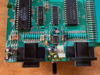
The route of the audio signal on my Vectrex is different to the buzzer units. It does not go to the power board at all. The amplifier IC is just next to the output to the speaker. I think there is also no C114. Have a look:

IMG_0320.pngThat’s the biggest design improvement on these later Models and thats why I can’t use our schematic unfortunately 😳

I am afraid I have to de- install the board again to check that area on the board. Actually I did this already months ago without success. But you are right - I should start with the volume control pot.
What I just realised….There are 2 audio signals combined you say. One from the 4052 and one from the AY3 sound chip. How does it work to generate analog audio? I only see square waves on the AY3 outputs…

Both ICs I tested ok in my other working Vectrex. So that’s something we can rule out. But maybe something is wrong which drives either IC?
 
Analogue audio... Don't make me laugh...

Yes, it would significantly help to find the real schematic for this board wouldn't it...

Dave
 
Ok. Got it. It’s only digital sound. We are talking about technology >40 years old although the Vectrex sounds a bit analogue sometimes 😁
 
Back
Top