• Please review our updated Terms and Rules here

Vectrex (newer version - no buzz) - Troubleshooting Sound but no Video

So that's interesting...

Can you identify what the upper and lower voltage levels are on Q505 emitter and collector please?

Dave
 
Thanks.

So we are talking about very small voltages - and very small currents.

I think what you are observing as signals on Q505 collector and emitter are as a result of the Z-axis attempting to switch on Q505.

Looking at Q505 emitter you say that the voltage switches between 0V and +0.18V. I suspect this to be as a result of the base current flowing from the Z-AXIS signal, through R513 into Q505 base. The current then flows through the emitter resistor (R515) and a voltage difference is generated across R515. Dividing 0.18 Volts by 150 Ohms gives me 1.2 mA of current.

The signal on Q505 collector is a 'strange amplification' of the Q505 base/emitter current - but with a very limited voltage source.

I suspect that Q503 is switched OFF and this is leading to all of our problems.

The circuit in the base of Q503 works as follows:

The Y-DRIVE signal is monitored via R417 and C409. C409 acting to block any DC component of the Y-DRIVE signal - thus permitting the actual deflection voltage change through. D402 shunts any negative voltage pulses to 0V/GND. D401 passes positive pulses through to charge up C410. R530 acts to discharge C410 when no input pulses are present.

Under normal circumstances, positive deltas of the Y-DRIVE will charge C410 and it should stay charged as long as there is Y movement (in one direction). The voltage that has built up on C410 is limited to 6.2 Volts by the series resistor R503 and zener diode DZ501. The resulting voltage is passed via R510 to the base of Q503 - thus turning it on.

Basically, when Y-DRIVE signals are present, Q503 should be turned ON. When Y-DRIVE signals cease, Q503 turns OFF.

When Q503 turns OFF, the CRT cathode gets pulled up to +50V via R512, and transistors Q401 and Q402 are turned OFF via Q504.

Now I have a problem - because I have a 'chicken and egg' situation. If I have turned off Q401 and Q402 - I have seriously reduced the X and Y drive signals to IC401. This, in turn, limits the Y-DRIVE signal that I am monitoring in order to turn Q503 ON (and hence turn Q401 and Q402 ON).

I am not sure how this circuit is now supposed to work - I am missing something here...

We could try an experiment to see if we can stimulate the base circuit of Q503 to operate, so we can see whether that 'fixes' the problem or not. If not, it may give us some additional information in order to help us diagnose the fault further.

What I am thinking of is to temporarily connect a resistor to supply some volts to the monitoring circuit to cause Q503 to switch ON. We might need to do this via a pushbutton to ensure that if anything else is wrong, we don't damage the CRT by burning a spot on it. Let me think about this a bit more, and let me have a think and a read about how this circuit SHOULD work correctly.

Dave
 
Wow. 😳 Very complicated circuit and difficult to understand. At least for me. How much voltage is necessary to switch Q503? Maybe I can use a little battery for that purpose? Or a flying wire with a switch connected to a power rail at the board?
 
I think 5V to 7V is adequate.

I think we need to add a series resistor though to be on the safe side.

I think we also need a diode in series as well (just to prevent any 'back voltages' from doing any damage just in case things start to work correctly).

Let me think before we do though...

Dave
 
Hi. Today I received replacement parts for Q503 and I thought why not just replace it. It’s easy to perform. So I did. But no change on the display but… now I see a little white dot in the middle of the screen. But only when I turn the brightness all the way up. I did not see that before and I was trying many times before. Not sure what it tell us. At least the high voltage transformer is ok, right? I scoped around the transistors Q503, 504 and 505 and it’s still the same status….
 
It is great that you have a dot on the screen.

Can you check the signals on the collector and emitter pins of the three transistors again please.

There has been a change, there has to have been.

Unless turning the brightness control up has sufficiently biassed the CRT to cause the spot.

Dave
 
Hi Dave. So I did. Got exactly the same results as in post #78. The spot is only visible when I turn the brightness to absolute maximum. Turning lower and the spot suddenly disappears 😳
 
Ok.

So it probably did that before.

I think we go to the temporary battery test.

Have you got a 9V battery (not a mains power supply) a 1k resistor, a diode and a normally open pushbutton?

Dave
 
Any conventional diode (not a Zener or anything like that) will do.

We just need it to block any higher voltages generated by the Vectrex (if it kicks into life) from feeding back to the battery. However, we do have the resistor in series and we are only talking of a few Volts differential. But I like to be sure...

Dave
 
Ok. Sounds like a good plan👍😊 So, coming from the positive battery lead through the diode and one 1k resistor to the base of the Q503. And the negative lead of the battery connects to ground of the Vectrex?
 
I would put the battery across C410. Battery negative to 0V and everything else (pushbutton, resistor and diode) in series with each other) to the positive side of C410. The diode should 'point to' C410.

Dave
 
Ah, but it has told us something new - has it not...

You now need to look at the signals at the collector of Q503 (with the switch both OFF and ON) and the collector of Q504 (with the switch both OFF and ON).

The 'battery' test has given us a good clean bill of health for the monitoring circuit (at least from C410 onwards) and I suspect our two transistors (Q503 and Q505) are also healthy - these drive the CRT cathode voltage.

There still remains the question regarding Q504. This test will indicate now where we go next.

It is always good when something does burst into life. After that, to see a change in the symptoms tells us something new - so that is the next best outcome. It is always a bit dismal when we get neither of these outcomes! But we just have to pick ourselves up and try something else...

Dave
 
That’s great news. Good to know at least the CRT is seemingly ok. I will do your suggested investigations likely not before Monday as we are on a lake over the weekend. Have a nice weekend, Dave🖖😊
 
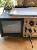
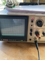
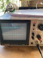
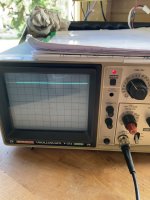
Hi Dave. Indeed, with this little kick the signals are now much different:

Q503-C OFF: 50,8V ON: 41,7V
Q504-C OFF: -19,0V ON: +5,45V

I used 5V/div. For Q503 I needed to shift the zero sweep all the way down (Offset ca. 25-30V) to see a waveform and for the Q504 the sweep was centered.
 

Attachments

  • Q504-C ON.jpeg
    Q504-C ON.jpeg
    1.3 MB · Views: 2
  • Q504-C OFF.jpeg
    Q504-C OFF.jpeg
    1.4 MB · Views: 2
  • Q503-C ON.jpeg
    Q503-C ON.jpeg
    1.4 MB · Views: 3
  • Q503-C OFF.jpeg
    Q503-C OFF.jpeg
    1.2 MB · Views: 2
Back
Top